
Projects:
GTO
My
67 Pontiac GTO
Trunk Body Work
-Trunk pans
-Wheel wells
Body Work Part 1
-Rear Quarters
-Rear Door Jambs
-Window Reveals
Body Work Part 2
-Cowl
-Pillar
-Rocker
Body Work Part 3
-Windshield channel
-Doors
-Fenders
GTO Paint
-Filler work
-Priming
-Blocking
GTO Frame Work
GTO Convertible Top Pt 1
-Top Frame
GTO Convertible Top Pt 2
-Top Trim
GTO Drivetrain
-Engine
-Quadrajet Rebuild
-Exhaust
-Axle
Muncie
Rebuild
popular
Auto to Manual Swap
1967
Ram Air GTO
story
Wheelhouse Filler template PDF
Willys CJ3A
CJ3A Intro
Engine and REBUILD
Drivetrain
BodyWork 1
BodyWork 2
BodyWork 3
BodyWork 4
Paintwork 1
Paintwork 2
Final Assembly
Final Assembly 2
Electrical System
Other Rods
TJ Wrangler Rubicon
CJ7
CJ8
Decrepid Dakota
Powerdyne Minibike
Allis Chalmers B engine rebuild Part 1
Allis Chalmers B engine rebuild Part 2
Allis Chalmers Generator to Alternator conversion
Gizmos
Stereo camera
rig
Stereo mic preamp
About:

Feeds

Markup
Allis Chalmers B Engine Rebuild
I married into a family that has a small farm with some cool old tractors. They still get some use once in a while and have not quite faded away. One of them is a 1950 Allis Chalmers B. The ol "B" was getting pretty unreliable and needed an overhaul to get it back to normal operating performance. My bother-in-law and I volunteered to rebuild the engine.
The Allis Chalmers engine for the "B" seems to be of a typical design from those days; reliable, low compression, and field rebuildable. It is a wet liner design, that is, it has removable cylinder liners that can be replaced without need for machining.
So that means I could rebuild the thing in my garage without worrying about getting outside machine work done. All we needed to do was place orders for a rebuild kit, get the engine into my garage and go to it.
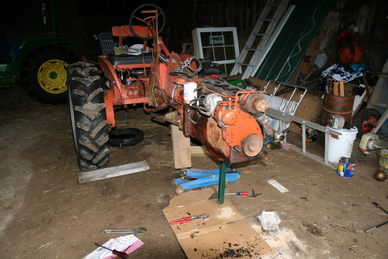
I thought it would be cool to document the rebuild, so what follows is how we went about it. Here is the "B" along with an old Farmall. This picture is after the B was rebuilt.

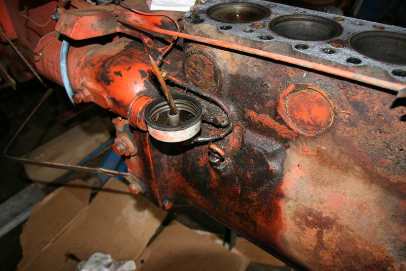
Below is a picture of what we started with:
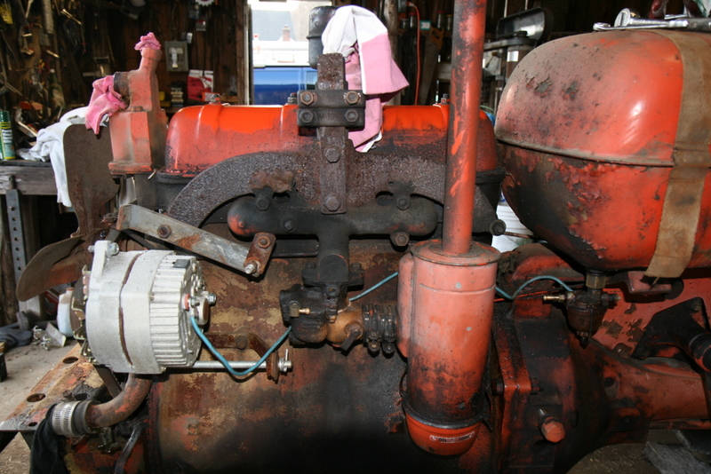
The engine had a huge oil leak, holes in the exhaust manifold, the magneto was not wired up with a shut off switch, the 1 wire delco alternator conversion did not work, and oil pressure was very low.
Teardown is no problem on a simple machine like this. Here is a shot of an external oil line to the built in governer housing. Note the magneto (for ignition spark) is mounted on the backside of the governer housing. Magnetos mean no need for a distributor, coil and battery. Early "B"s did not have batteries. Later "B"s like this one did come with 6V batteries, but only for the starter system and lights if so equipped. I think even later "B"s eventually had conventional distributors with a coil.
Separating the engine from the tractor involves taking off the front end and then unbolting the engine from the torque tube.
We removed the oil filter and were shocked to find that a wooden dowel was put in place of the original oil supply tube. This thing had been running for years with a blocked oil passage. It probably broke off decades ago and the mechanic didn't realize it was an oil supply tube, so they put in a dowel instead(?)
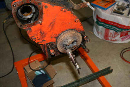
The engine was taken off and more teardown commenced. Here, I had to drill and tap holes in the front pulley in order to pull it off. That's the tap being shown.
The engine was flipped and the oil pan removed. Note the safety wire installed on the main caps.

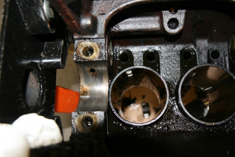
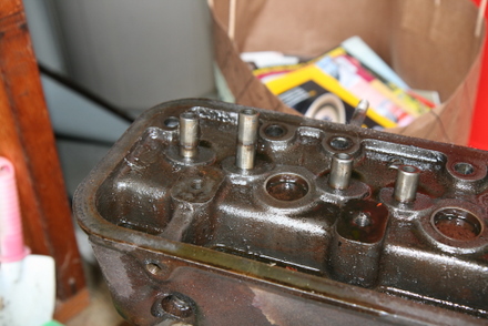
In the photo below, note the surfaces where the main caps were. You can see spots where there were shim packs installed. These engines were built with shims that gave the proper tolerances between the crank journals and bearings. The shim packs were of the peel-able kind; a 0.010" shim was actually 10 layers of 0.001" shims. If you wanted to take out slop or excess gap, you could simply peel a layer or two from the shim packs, reinstall, and your tolerances would be back to spec.
Also note how the cylinder sleeves stick through into the crankcase. As mentioned before, this is a wet liner engine; the cylinders are actually "liners" that fit into the engine block. "Wet liner" I believe means that coolant is in contact with the liners. The liners are press fit into the engine block. I put the engine block with the head surface down on some 4x4 blocks. From above, using another 4x4 block end-on on the liners, I whacked them out with a few taps from a sledge hammer. Sorta gentle-like.
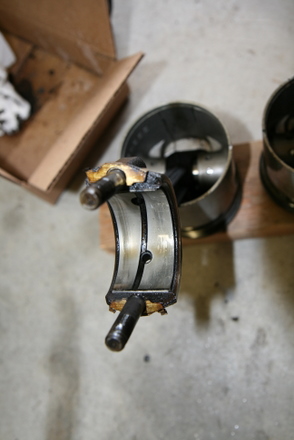
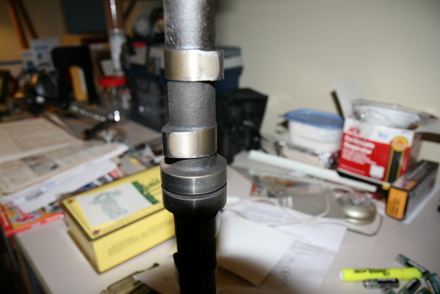
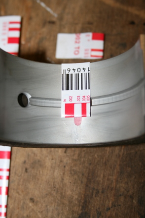
Here's a shot of one of the piston rods. These also use brass shims to set the tolerances. The peel-able shim is still in place on the rod.
Overall, the engine was in great shape. The bearings were worn, but showed no signs of scoring or overheating.
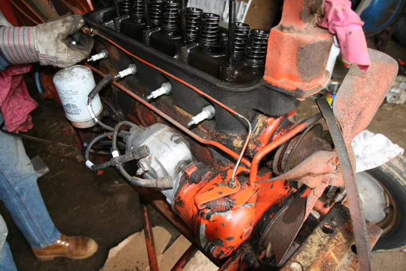
The head also features replaceable valve guides. They can simply be pounded out and new ones pressed in. Here you can see I've started to pound one of them out.
The valvetrain is mechanical and used tappets which then actuate pushrods.
The cam was in good shape too.
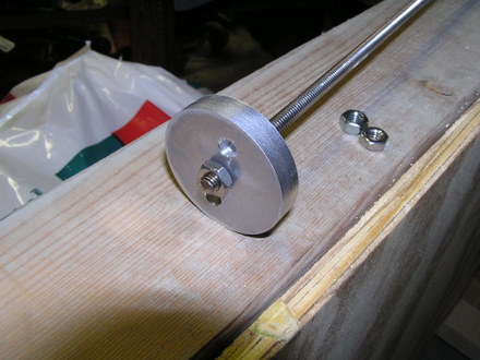
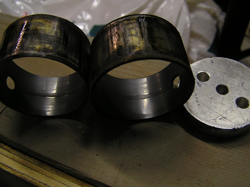
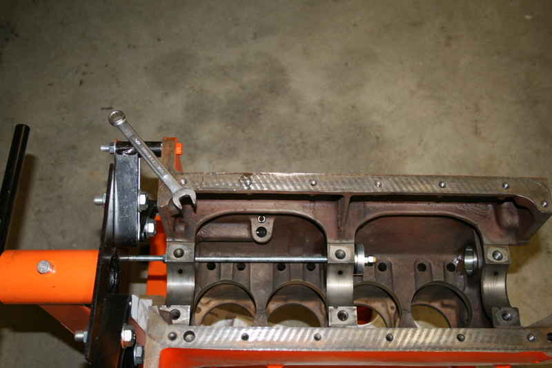
Once the block was torn down, it was time to remove the cam bearings inside the block. I fabricated a round plate that would fit inside the bore and pull out the bearings using threaded rod with nuts to provide pulling force.
The threaded rod was a 1/4-20, which ended up being too small. The rod actually stretched and didn't budge the bearing. So while under tension, I used a hammer to smack the plug, and POW!....the bearing shot out by about an 1/8 of an inch. It pulled out normally after that. I had to do that with all of them. All cam bearings pull out toward the front of the engine.

Note also the removal of the cylinder liners, and that the inside of the engine block was painted with some kind of brown paint. I've learned that this may have been common in the old days.
The cam bearings were quite worn, probably about 0.008 or so. Note the ridge in the center areas. This would definitely hurt good oil pressure.
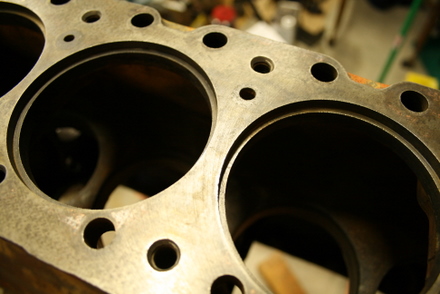
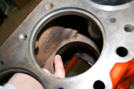
The block was cleaned and washed a bunch of times, but each time I'd find something else to nitpick. This is one of the chamfers (tapers) in the lower part of the block. The liners feature O-rings that seal the lower part of the liner from the crankcase. The o-rings must pass by this chamfer when driving the cylinder liner down through. These chamfers are exposed to the coolant and thus collected sediment. It was tough to chisel these clean.
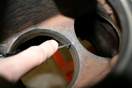
I found a crack between the center cylinder holes, (hard to see here) but apparently this is common.
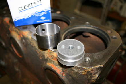
I made a new cam bearing installation plug which featured a pilot area (a step) in order to help center the tool while pulling the bearing into the block. I also went to a bigger 3/8-16 threaded rod.
And the cam bearings were installed. These are installed from the front toward the back.
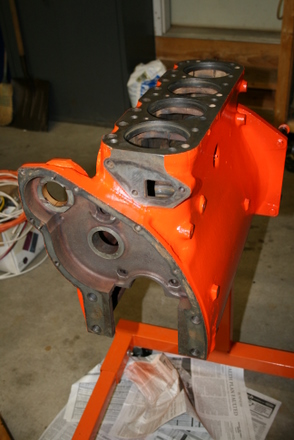
The engine was painted with awful Tractor Supply paint cuz that's all we had.
Assembling Engine and Measuring Shim Thicknesses
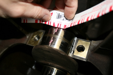
Before installing the cylinder liners, I wanted to install the crank and main bearings and check for fit. As mentioned before, these engines use shims under the main caps to set the bearing clearances. The original peel type shim stacks were in tough shape, so I got a bunch of different thicknesses of brass shim stock and made my own shims as you can see. I started with the nominal thickness shim set of 0.010" under the main caps to see how close I was to spec. Here you can see my plastigage tells me my clearance is about 0.004". Spec is on the order of 0.002", so I must make thinner shims.
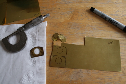
Here is a sample of the shims I made. On the left is an original, on the right is some brass shim stock that I'm using to cut out new replacements. This stuff I'm using is not the layer type, so I'll just find the correct thickness and cut out my shims from that.
Since my clearance is too much, I'm going to reduce the shim stack thickness by 0.002 (to 0.008"). I need to correspondingly reduce the height of the bearing shells so they won't pinch each other too much when torqued down. You are supposed to have the shells "too tall" by 0.0015" on each side so you get a "crush" when you bolt the cap down. This ensures the bearing shells are jammed into the bearing saddles and bearing caps. When reducing shim stack thickness, you must grind off some of the bearing shells, or the "crush" will be too much and it'll pinch or fold into the crank creating a binding situation. Here, I'm grinding down a bearing shell on 600 grit. I'm using my kitchen counter as a grinding surface. I only ground down the top shell. I removed about 0.0015 or so when I removed 0.002" from the shim stack. So it's about a 75% ratio of bearing shell height to the difference in shim height.
I bolted the whole thing up again with the new thinner shim set of 0.008" and the new main bearing clearance measured is about 0.003". I decided to stop here. I think I'd rather try this, and if it turns out the oil pressure is too low, I'll go thinner.
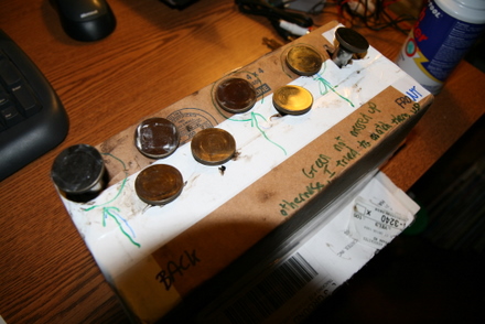
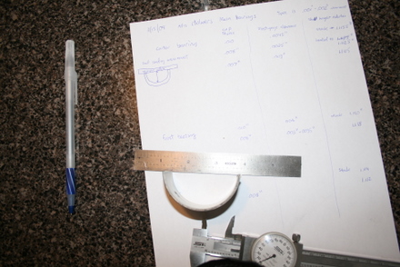
I made a chart to track each set of bearing shells and their associated shim thickness. I also tracked how much I gound off each bearing shell when compensating for altered shim thicknesses. I used a dial gauge to measure how much I was changing the bearing shell height.
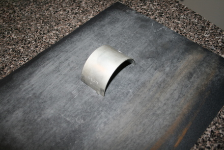
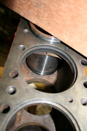
With the clearances all set, it was time to put in the cylinder liners. This one, shown upside down, is ready to be put in. Note the two o-rings that have been installed on the liner. They've been lubed up with dish soap so the o-rings will slip right into the block.
Here is the taper in the bottom of the bore in the block that the o-rings must squeeze into. I've added liquid soap here too.
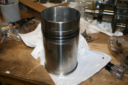
Here's the liner ready to be tapped "home".
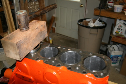
The last liner is being tapped into place. Nice shiny, honed cylinder bores. Very nice to be on a clean part of the job now.
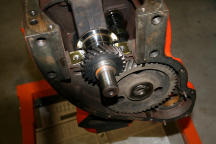
The cam was installed and the crank was then dropped in. Note the brass shims where the main caps go.
To see Part 2 of the Allis Chalmers B engine rebuild, GO HERE
To see the Alternator conversion, GO HERE
SFS
Links:
Willys Jeep CJ3A Forum
There exists a nice set of webpages for CJ3A's. It's got a forum too that caters to both '3A's and CJ3B's. It's a great resource, and frequented by very knowledgible folks.
1967 GTO Original Owner
These two videos feature an original owner GTO. This car was featured in Hemmings Muscle Cars magazine a couple years ago. Part 2 has inside and outside shots of the owner driving the car. Very nicely done.
Blues Maker
"Mississippi" Fred McDowell. One of the great Bluesman. This is a documentary made in 1969.
Pinstripes
Pinstriping the ol' fashioned way. Pretty nice.
MGB Racecar
I've always liked MG's. Watch this MGB lift it's inside tire a few inches off the tarmac when going "'round the bend". Awesome.
Pepsi Throwback

Pepsi has put out a "limited edition Throwback" version of Pepsi with REAL sugar, instead of high fructose corn syrup which has been used since the 80's. Holy cow there IS a difference; it's WAY better. Find some quick!