

Projects:
GTO
My
67 Pontiac GTO
Trunk Body Work
-Trunk pans
-Wheel wells
Body Work Part 1
-Rear Quarters
-Rear Door Jambs
-Window Reveals
Body Work Part 2
-Cowl
-Pillar
-Rocker
Body Work Part 3
-Windshield channel
-Doors
-Fenders
GTO Paint
-Filler work
-Priming
-Blocking
GTO Frame Work
GTO Convertible Top Pt 1
-Top Frame
GTO Convertible Top Pt 2
-Top Trim
GTO Drivetrain
-Engine
-Quadrajet Rebuild
-Exhaust
-Axle
Muncie
Rebuild
popular
Auto to Manual Swap
1967
Ram Air GTO
story
Wheelhouse Filler template PDF
Willys CJ3A
CJ3A Intro
Engine and REBUILD
Drivetrain
BodyWork 1
BodyWork 2
BodyWork 3
BodyWork 4
Paintwork 1
Paintwork 2
Final Assembly
Final Assembly 2
Electrical System
Other Rods
TJ Wrangler Rubicon
CJ7
CJ8
Triumph TR4
Decrepid Dakota
Powerdyne Minibike
Allis Chalmers B engine rebuild Part 1
Allis Chalmers B engine rebuild Part 2
Allis Chalmers Generator to Alternator conversion
Gizmos
Stereo camera
rig
Stereo mic preamp
About:

Feeds

Markup
CJ3A Electrical System
When I picked up this old CJ3A it still had its original cloth covered harness and 6 volt generator. There were a few patches hither and thither performed over the years to keep it going, but age and neglect ultimately rendered the wiring unsalvageable. The generator was crusty and sticky too. My enthusiasm for replacing and rebuilding all the 6 volt parts was dampened when I added up the costs of a new cloth covered wire harness and generator rebuild. So I investigated converting to a 12 volt system as a less expensive alternative.
There are universal 12 volt electrical system “kits” that offer everything you need, but they are relatively expensive and have features a simple CJ3A wiring system doesn’t need. Jeeps originally used ring terminals on most every wire termination, so there’s no need for custom connectors or bulkheads. I found that all the piece/part components to make a scratch built 12 volt system can be sourced from local parts stores and online, and it can be put together with a soldering iron, heat gun and harness tape. Doing it this way keeps costs well below the stock 6 volt restoration, and the practical benefits described below are hard to beat as well.
12 Volt System Components
After spending a little time looking over electrical schematics for cars from the 60’s to 80’s, I came up with a simple system that supplies plenty of power, utilizes fuses and relays for safety, and can accommodate extra circuits for turn signals and a heater motor. These are some of the components that this system will use:
- Delco "3 wire" alternator (internally regulated)
- Fuse panels: one 6 circuit (always hot), one 6 circuit (hot when keyed ON)
- Bypassable ballast resistor for hotter spark during starting
- Signal Stat 900 turn signal mechanism
- Relays for headlamps and horn circuits
Besides swapping out the 6 volt generator for the Delco 3 wire unit, other 6 volt components will need to be changed or modified:
- 6 vollt ignition coil to 12 volt
- 6 volt bulbs and lamps to 12 volt
- Original Ammeter*
- Fuel gauge and sender**
- 6 volt starter motor***
- 6 volt to 12 volt battery
* Caveat 1) The original ammeter might work okay, but since current flow will be halved with a 12V system, you won't see much needle movement. You may want to consider changing to a voltmeter (which is what I did).
**Caveat 2) With a little work, the original fuel gauge/fuel sender set can be kept by using a simple home made voltage regulator (a device that steps voltage down to acceptable levels for the gauge and sender). Details below.
***Caveat 3) The starter motor can be operated at 12 volts as long as cranking times are kept reasonable.
Besides the presence of the alternator under the hood, these changes are pretty much invisible. The original Willys switches and dash lamp housings can all stay which helps maintain the vintage look.
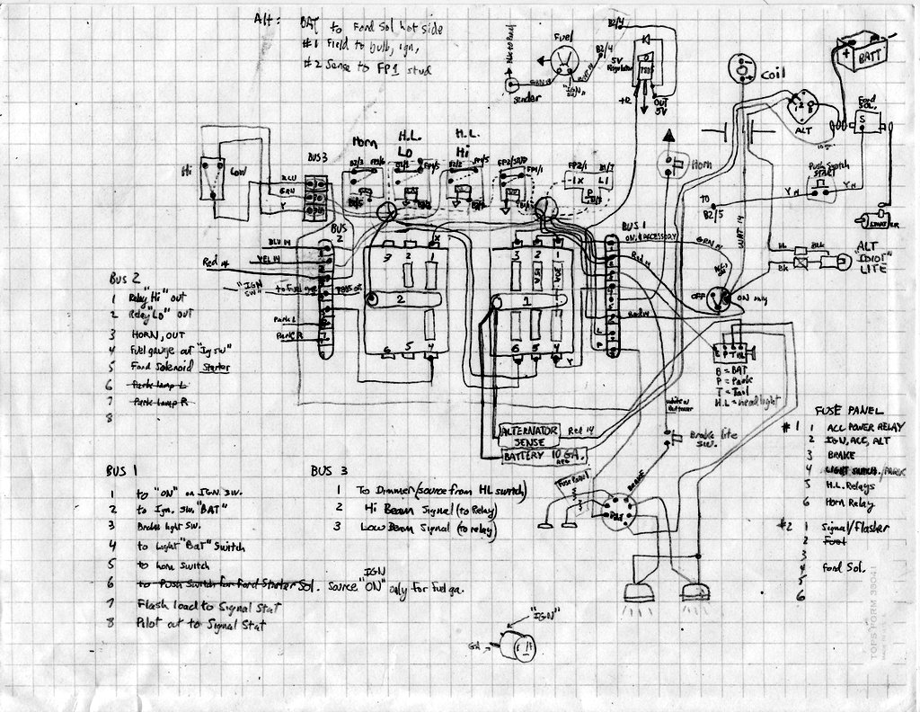
The Schematic
I sketched up some point-to-point drawings and settled on this:
I then made a finished, more schematic-like version of the design with a free "app" from digikey.com:
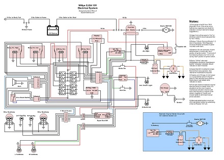
You can click on the schematic above and save it as a PDF file.
With the design in hand, I started in on the system build:
Fuse Panel
The original electrical system was spartan and had no central
"fuse panel". But with all the new parts required with the conversion, I needed a panel to house all these things in a central, hidden, yet easy to access location. Here are the things I want to put on the panel:
Fuse Blocks:
I wanted to use standard large spade type fuses. There are quite a few options available on Amazon and I selected a very simple 6 position unit with 1/4" spade connections and a central stud feed.

I chose to buy two blocks and wire them separately: One is fed with an always "hot" source from the battery, and the other is to be "hot" only when the key is in the ON or ACCESSORY postition. This follows typical convention; the always hot panel feeds lights, horn, and ignition switch, and the switched panel feeds turn signals and future options such as heater blower motor.
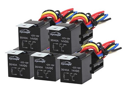
Relays:
I used relays primarily to avoid running high current through my original switches (which is good for them and safer too). I bought a 5 pack of standard type relays (with sockets and pigtails too) from Amazon also.
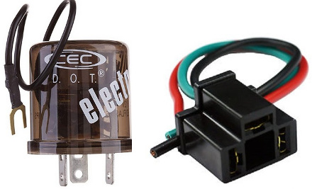
Flasher:
I needed a flasher can for my Signal Stat turn signal set up, so I purchased a CEC flasher can that is compatible with LED lamps which I intend to use in the grille parking lamp locations. I got a standard 3 pin socket to fit that to the panel.
Voltage Regulator:
As mentioned before, I wanted to keep my original fuel gauge/sender which can only be used with a 6 volt system. To keep it, I would need a regulator to cut down the 12 volts to 6 volts. You can buy ready-to-use reguators, but you can also make your own. There are IC chips that can do this for you which can be purchased from (yep) Amazon also. I used a 7805 IC chip which regulates down to 5 volts. There is a 7806 chip which regulates to 6 volts, but I found that my gauge worked fine with 5 volts. These IC "chips" are crazy cheap; something like 10 pcs for 6 bucks. They can handle up to one amp which is fine for just the fuel gauge. You can simply ground it, feed it 12 volts and it will output 5 volts. See the schematic for pinout.
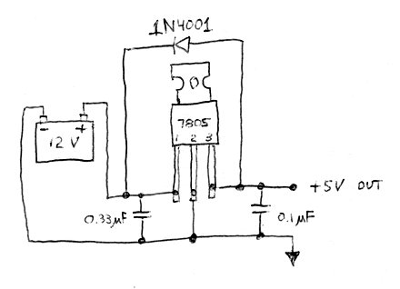
I installed extra components as shown on the Texas Instruments datasheet. It is recommended to use capacitors to help smooth output, which is probably not necessary for use with battery power but I did it anyway. Note too the diode for some reverse polarity protection.
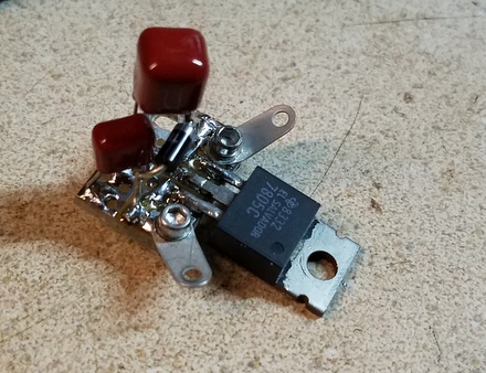
I used a tiny piece of "perf" board, soldered in the capacitors, and also two solder tabs for the input and output leads. The "circuit" assembly was screwed to the fuse panel plate through the metal tab of the IC chip which also serves as a heat sink if the chip gets hot. The 5 volts is fed to the gauge per the wiring diagram.
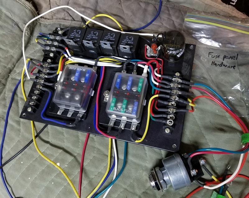
The Fuse Panel:
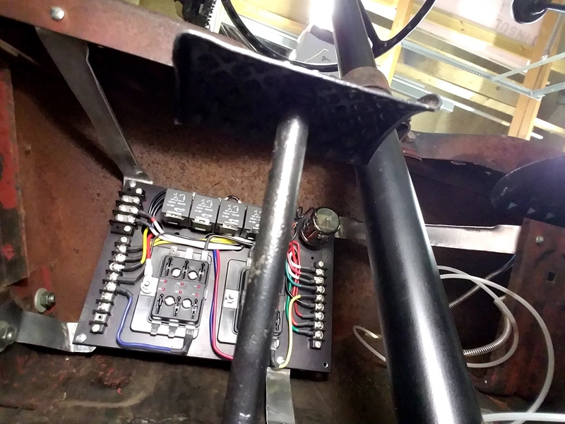
I fabricated an aluminum plate with enough space to fit 4 relays, two 6 position fuse blocks, the turn signal socket, and the voltage regulator (reducer).

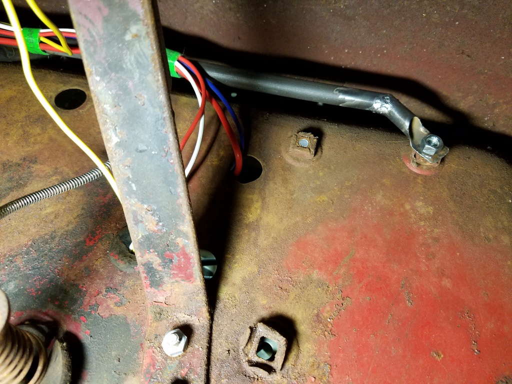
I decided to suspend it under the dash on the driver side with four brackets that I just bent up from scrap. It is completely out of sight but accessable for maintenance. Ignore the clutch pedal in the foreground (picture below).
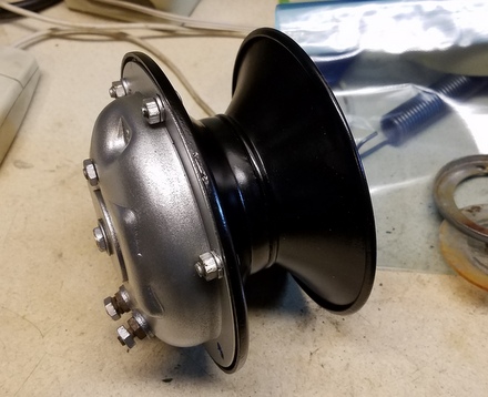
Charging System
Likely the cheapest and most reliable charging system option is a classic Delco alternator. The early ones (like the 10DN) require external regulators, so consider the later 10SI and 12SI with internal regulators which means less wiring. There are millions of them in use out there and odds are good you can find one at swap meets, recyclers, or parts stores.
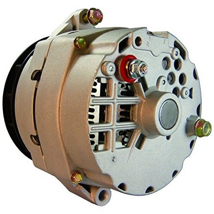
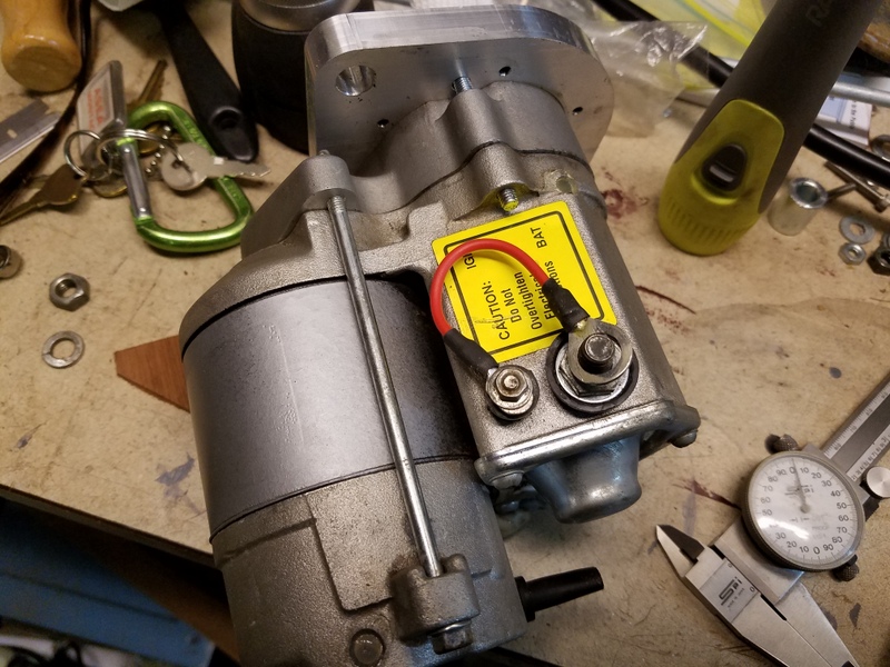
I went for a rebuilt unit at my local parts counter. I requested an alternator for a 1980 Camaro V8 and they handed me a Delco 12SI. This unit is a bit heavier duty than the 10SI so I was happy to go with this one. These OEM style units feature 3 wire hookup which, according to my research, are superior to aftermarket "one-wire" alternators. (Do some research and I think you'll agree.) Note the two terminals at the top labeled 1 and 2, and of course the "Bat" stud.
I adapted the 12SI unit to the engine with a home made bracket, but if you're not handy, a bracket can be had by some Jeep suppliers online.
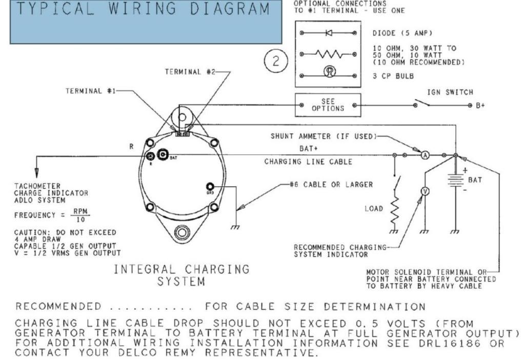
The Delco "3-wire" alternator hookup connections consist of:
1) Field (Terminal 1)
2) Sense (Terminal 2)
3) Battery (BAT)
The BAT (battery) terminal stud feeds power to the battery. Typically, 8 or 10 gauge wire is used. Depending on vehicle, the wire can be run directly to the positive terminal of the battery, or a more convenient location such as to the "hot" side of a horn relay or starter relay. I chose to wire it to the starter stud of a Ford style starter relay. Note that it is wise to wire in a fusable link in series with this wire. Take a look at my schematic above and you can see the details.
The Field (Terminal 1) on the alternator is basically how the alternator is turned "on". A wire is run from the ignition switch "ON" terminal to this Field terminal. It can be a light gauge wire (I used 14 gauge because that's what I had). A diode, resistor or incandescent bulb must be wired in series with this wire; this basically prevents the alternator from backfeeding voltage to the coil when you turn the ignition off (backfeeding would prevent the engine from shutting off). I like the idea of using a bulb, since it also functions as a charging indicator (otherwise known as an "idiot light"). I found what I believe to be a Delco schematic with the three recommended ways to wire this feature into the field terminal circuit:
The Sense (Terminal 2) samples what the voltage is in your system at all times for the voltage regulator inside the alternator. Best practice is to run a wire from a point closest to where your electrical power is distributed. I run mine right to the "always hot" fuse panel stud. This tracks voltage drops from your accessories most accurately. However, some folks simply jump it a few inches to the "BATT" stud on the back of the alternator. (I did it this way on my Allis Chalmers 12 volt conversion page.)
There's actually a 4th connection too: A ground. The mount I used on the engine will provide a decent connection to earth ground by itself, so I won't need a discrete ground wire to the alternator housing.
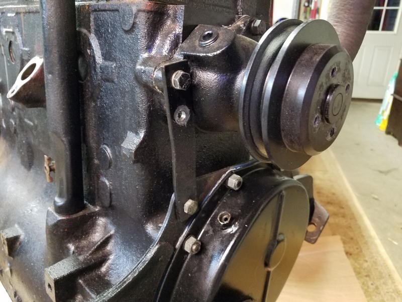
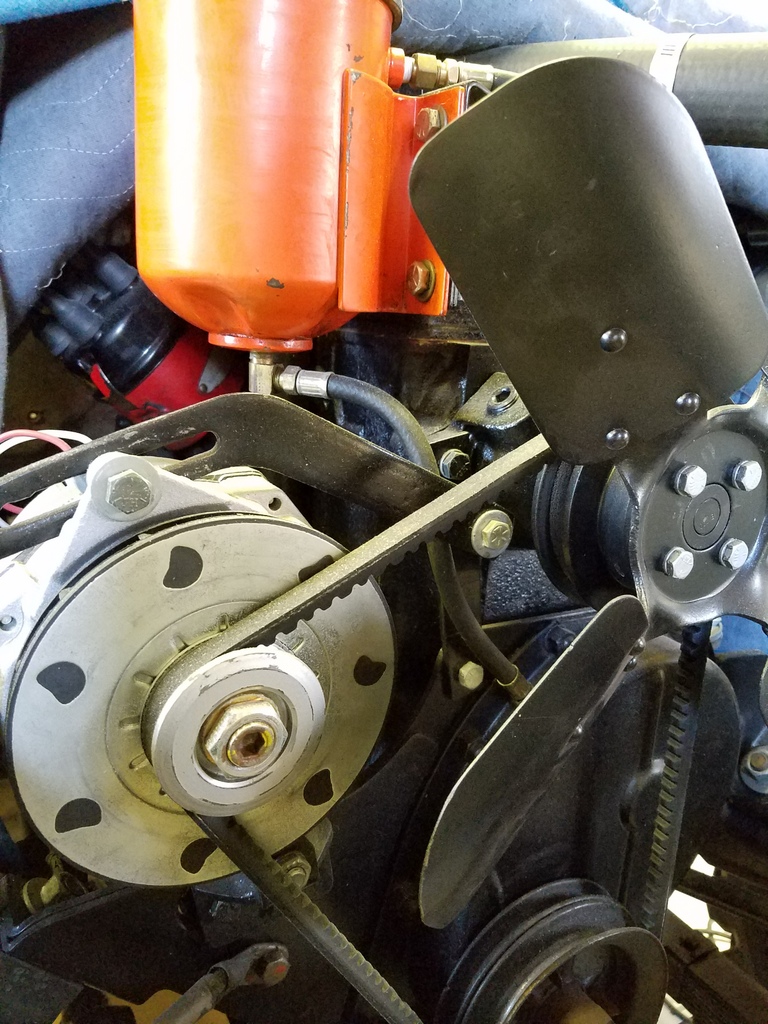
A note about mounting the alternator to the engine: I made my own bracket to fit the base of the alternator to the engine plate. Mine looks much like the ones that folks sell online. For the top adjustable strap, lots of folks use the original adjuster strap for the generator and use the nearest waterpump bolt on the engine end. There is an issue doing that however in that the geometry leads to binding of the strap on top of the alternator. Moving the end of the strap down a little bit will prevent binding but of course there's nothing to bolt to.....unless....you make up a metal strap that spans from the waterpump bolt boss down to the top of the engine plate where there is a convenient hole. The adjuster strap can be bolted to the middle of that new strap (with a spacer) and the strap doesn't bind with the alternator housing.
Every application is unique of course, so just roll up your sleeves and make something work!
Starting System
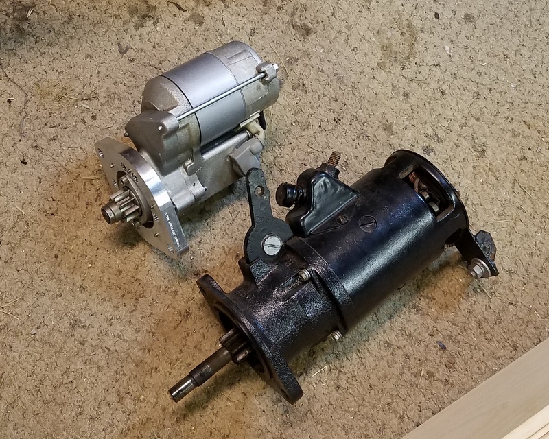
Original CJ3A starters are about as about as basic (electrically) as it gets. Run a battery cable to it. Done. The engagement is all mechanical...with your foot. I used my original starter for a while, but it was tired. They're expensive to replace. For later model 129 tooth flywheel L134's, and F134's, there is the possiblity of fitting a certain Toyota starter. But these 124 tooth flywheel Go Devils can't use that type of starter.
There are Denso OSGR (Off Set Gear Reduction) type starters made to fit 124 tooth L134's, but they're close to 300 bucks. I started looking into finding another candidate Denso to adapt to my engine, and stumbled upon a used, (20 dollar) aftermarket "Power Master" small block Ford starter #9504 which is based on the Denso OSGR. This one had an 11 tooth pinion, and of course a small block ford adapter. It looked like I could make it work so I started modifications.
I swapped in a new 9 tooth pinion which are readily available on the internet:
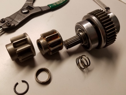
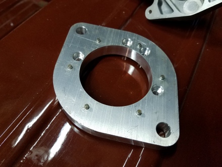
Then I made a zillion measurements and machined myself a new adapter (I am very fortunate to have a crusty benchtop CNC machine).
Can you tell which one is the Denso? (haha)
The power stud is on the wrong side, so I made a 3" copper bar extension so the starter cable attaches more easily. You can see it emerging from behind in the picture below.
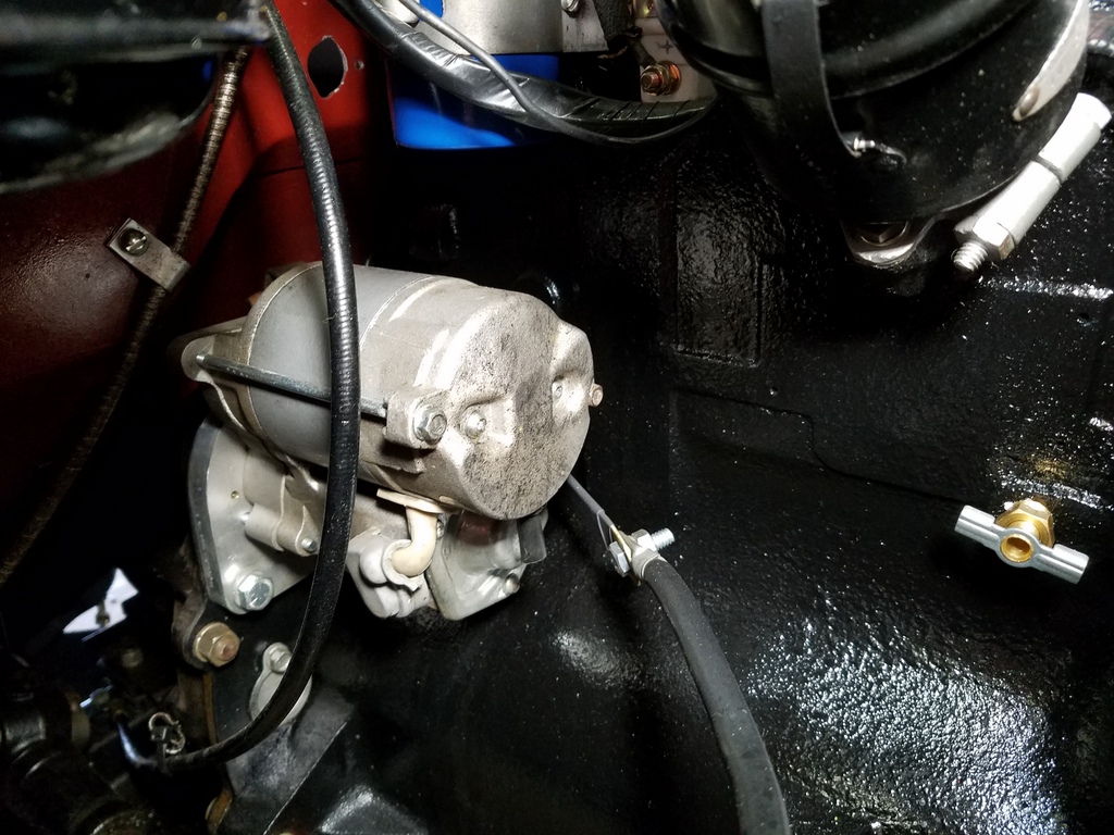
The Denso has a built in solenoid but I had already begun installing a classic remote Ford type solenoid on my passenger fender. The Denso solenoid can be bypassed by installing a short jumper on it's terminals.
I decided to stick with the remote Ford solenoid because I prefer having it close to the battery and alternator.
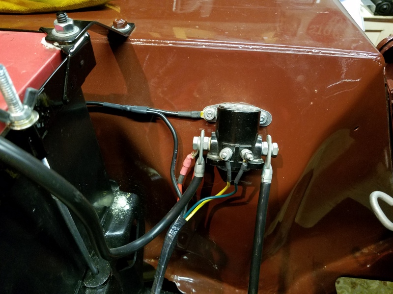
Ford solenoids have studs for the battery cable IN, and the starter cable OUT. Two small terminals on the side are "S" for "Start" which activates the solenoid to connect power to the starter. The other terminal is labeled "I" for Ignition. This can be used to provide a full 12 volts to your coil while the solenoid coil is engergized (operating the starter). Run a wire directly to the "+" terminal of the coil to bypass the ballast resistor. This boosts ignition power for cold starts. See wiring diagram for specifics.
The starter system works perfectly. I think another possible starter candidate would be a Harley Davidson Sportster starter. Those already have 9 tooth pinions, the power stud is on the correct side, and the front housings have features to bolt on an adapter plate. Of course you must still make a custom adapter for the 124 tooth flywheel Go Devil engine.
Ignition
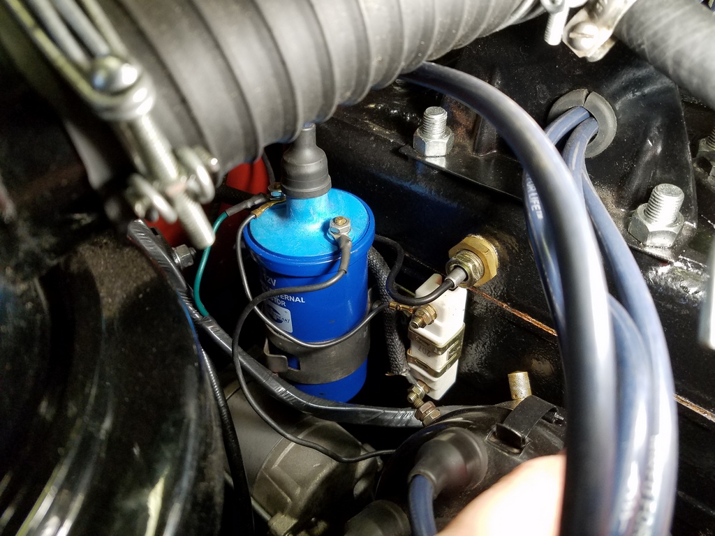
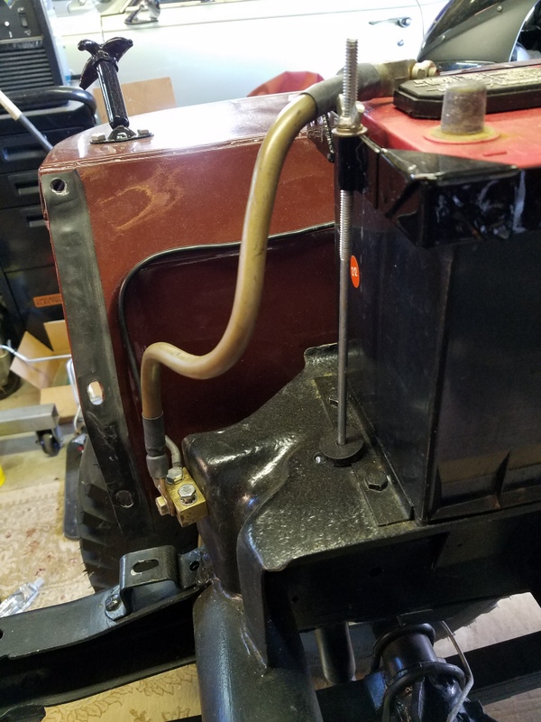
For the 12 volt conversion, I used a Standard brand (SMP) UC-12X coil which requires an external resistor. For that, I chose an SMP RU13T 1.6 ohm ballast resistor that has a convenient mounting tab. It's visisble to the right of the coil in the picture below. The power lead from the ignition switch goes to one side of the ballast resistor, then a lead from the other side goes to the coil "+" terminal.
Wiring
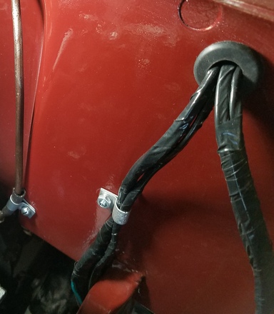
Original wire routing seemed to have simply been point to point on the switches and gauges under the instrument panel. There weren't alot of wires in the orignal setup, so this worked out okay. With the new panel and more wire to be routed, some order was necessary so I spanned a piece of scrap tubing across the firewall behind the dash.
I flattened the ends of the tube and fastened it (with nuts) to bolts that were sticking through the firewall. I zip-tied the wires (initially green velcro) that run from the fuse panel and along the firewall to this tubing as they exit out the firewall holes (no grommets installed yet in picture.) The tubing helps keep the wires neat and away from the speedo cable and parking brake cable. Some wires take a short route from the new fuse panel out to a hole on the driver side firewall and these didn’t need any support.
For wire terminations, I used simple crimp style ring terminals. I wired one circuit at a time. The terminal ends were crimped, then soldered, and I used heat shrink tubing around the joint rather than the cheezy plastic insulators that come on the connectors (pulled them off before using). It's much neater and less bulky with heat shrink. Solder makes it more reliable long term. Here's a closeup of the terminations on the fuse panel:
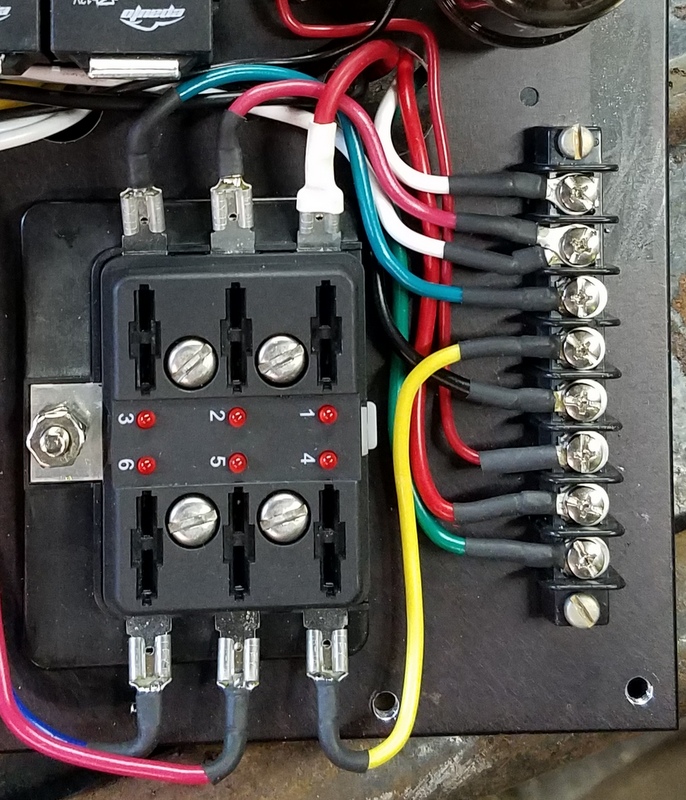
I should have used flag terminals (90 degree connection) on the bottom row of terminals but I couldn't find any locally, so I just used plain ol' straight spade terminals and bent the wires 'round.
Most all of the wire I used is new 14 gauge which is probably unnecessarily heavy duty for 12 volts, but it can't hurt.
I was going to use double row terminal strips on the fuse panel but since I had some old single row strips hanging around, I used those. Not a big deal. I also put a new single row terminal strip on the driver side fender. It has more connections than original to accommodate the additional wires needed for turn signals.
Head Lamps
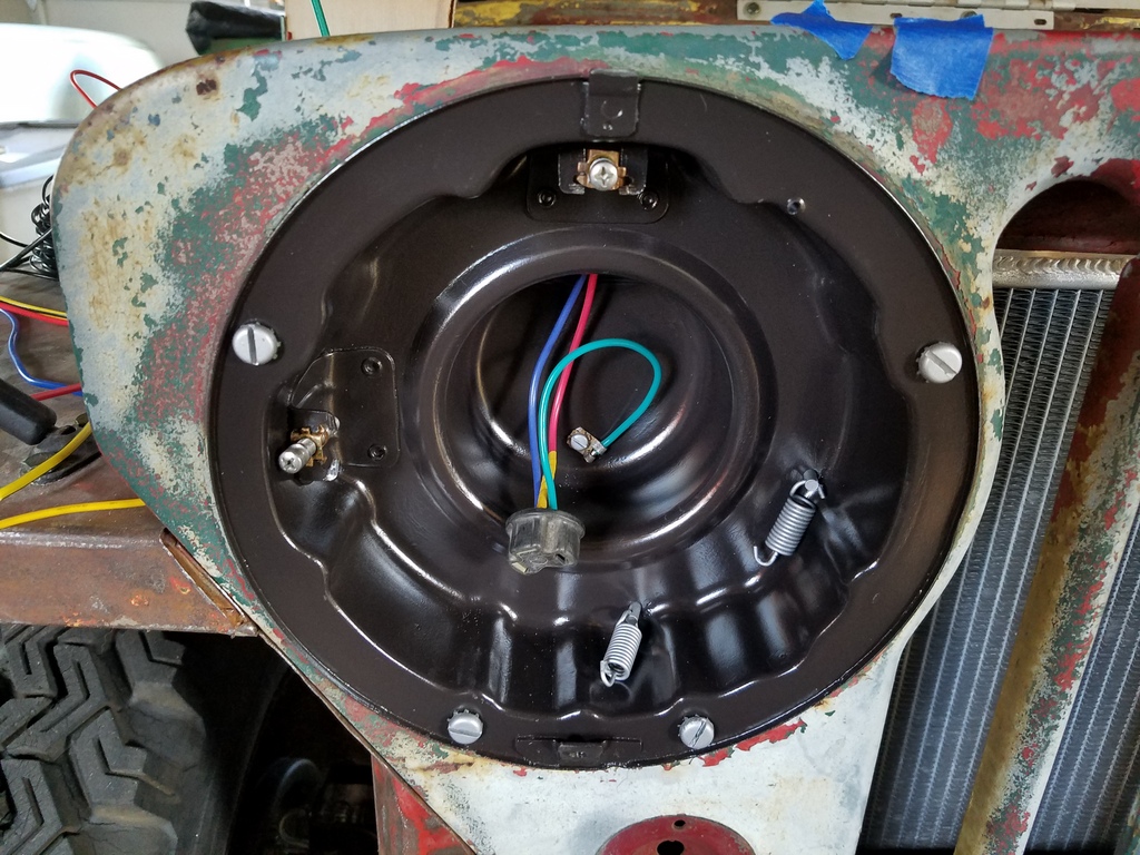
I love old stuff because a lot of it can be rebuilt unlike modern day stuff. For instance, I was able to press out the terminals of the head lamp sockets and de-solder the old wires from the terminal sockets and solder in new wire. I managed to save and re-use every original terminal, even the flag terminal on the end of the ground lead (which you can see in the back of the headlight bucket in the picture following this one.)
The headlight bucket is grounded to the vehicle through the 4 slotted screws with star washers. The headlight connector provides ground to the headlights through the short (now green) pigtail that is grounded to the back of the headlight housing.
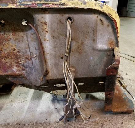
I was paranoid about grounding, so I installed a big brass block with provision for extra ground leads in the original battery cable ground location under the battery tray. The cable bolts to the frame through the brass block. (Note also my re-use of a vintage used 6V battery cable)
There are two threaded holes on top of the block that I can run extra grounds from. In the picture above, you can see a 10 gauge wire going from the block, up the fender and then towards the back where my starter solenoid is mounted. I branched off a lead to go to the solenoid case. The main lead keeps going through the harness and ultimately through the firewall and to the fuse panel plate. Right before it gets to the plate I branched off another spur 10 gauge wire to ground to a gusset behind the dash panel. Gotta have good grounds.
I ran another short 10 gauge wire (not shown) from the brass block directly to the bottom lip of the grille to ensure good grounds for the headlamps and parking lamps.
Bullet Connectors
Most wiring can run point to point with no breaks, but in some cases, it's convenient to have connectors for servicability. Bullet connectors were found here and there in the original harness (big hard plastic bakelite type construction) and they work great. I found and used new bullet connectors with soft rubber seals.
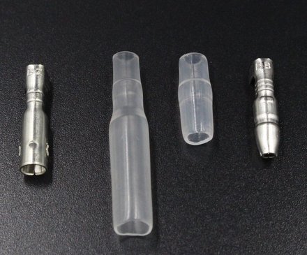
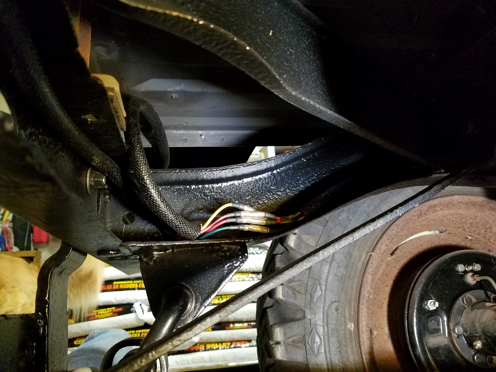
A dab of RTV silicone at the ends sealed the boots in place. Here are a set of bullet connectors for the rear tail lights tucked on the inside of the frame:
Tail Lamps
CJ3A’s were built with one tail light and no turn signals. Like many Jeep owners, I want to add both. I sourced a pair of used NACO style tail lamps to use. They are new-ish re-pops, and they have the same horizontal bolt pattern as the original tail light.
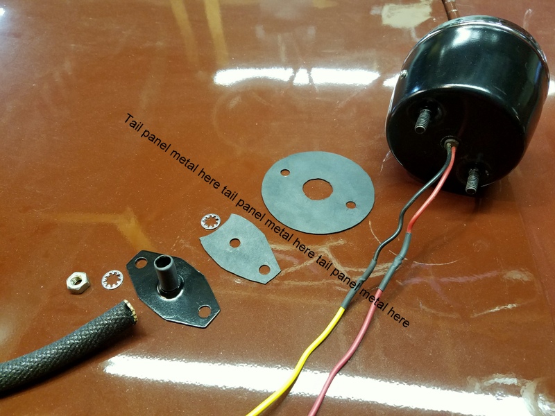
One thing I didn’t like about these lamps was the feeble seal where the wires exit the housing. Water kicked up by the rear wheels will overwhelm these seals. For better protection, I made some splash guards: I made sheet metal steel plates with two holes for the lamp studs, then drilled a center hole and used a tapered punch to deform a chamfer shape into that hole to which I placed short pieces of 3/8" copper tube. The tubes were soldered in place.
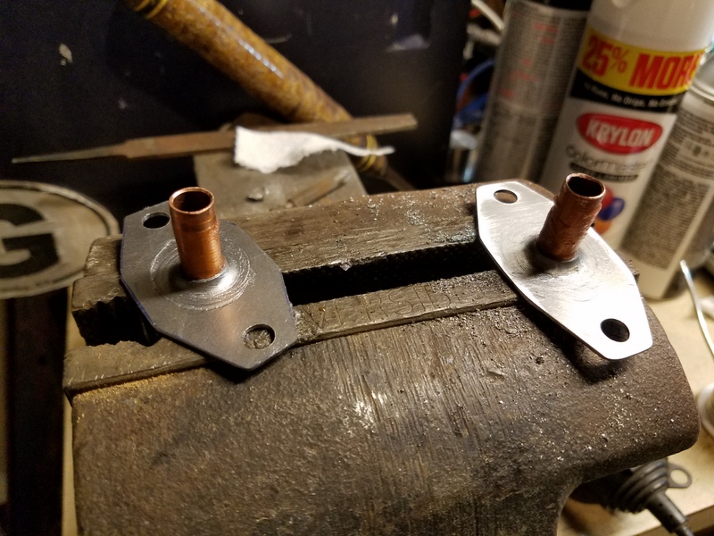
The flanges bolt onto the lamp studs on the wheel well side, then wire loom is attached to the tubes and the lamp wires run safely inside over to the frame. I used rubber gaskets on both sides to seal the whole assembly. In the picture below, I've laid out how it all fits (right to left): Lamp, round rubber seal, body tub, another rubber seal, flange, then the loom. I used spring clamps to hold the loom to the flange tube end. Note the star washers...they go on either side of the flange and help dig into the metal parts to ground the lamp housing studs.
Here it is installed.
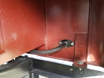
The tail light pigtails are terminated with bullet connectors and meet the wires coming along the frame from the front (see four pictures above).
Turn Signals (warning...this is a long one)
I found a 900 series Signal Stat turn signal unit to use on my CJ3A. The unit gets spliced into your existing brake light and parking light harness. Internally, there are electrical slides and contacts that "inject" turn signal power into your harness to "blink" your lamps.
Specifically, for the 900 series unit I have, the sliders and contacts are acting like two switches:
- REAR: The "switch" for the rear lights acts like a Single Pole Double Throw (SPDT) type switch: When the lever is neutral, the switch is set so that one throw, the one with the brake light input, connects to the lead going back to the brake light. When the lever is turned, the switch connects to the other throw that has the the turn signal blinker as its input. So the SPDT "switch" allows one of two inputs to pass to the rear brake light filament. Obviously, this function only happens on one side or the other depending on the lever.
- FRONT: For the front lamps, unfortunately, it has only one "throw", that is, it's like a Single Pole Single Throw (SPST) switch. When the lever is neutral, there is no input to the lead going to the front lamp. When the lever is turned, the switch connects the single throw to the output lead going to the front lamp. So that means whatever lamp you choose for the front, it can only be a turn signal. It can't be a parking light when the turn signal is off.
Since CJ3A parking lamps have only single filament sockets I would have to give up my parking lights in order to use this 900 series Signal Stat to provide turn signals.
Possible Solution #1: Remove the single filament bulb sockets in the grille and put in dual filament bulb sockets: Then, one set of filaments would be dedicated to the new turn signals, and the other pair of filaments could serve as the parking lights (completely separate from the Signal Stat unit). Doing this modification can require drilling out the grille. I didn't want to do this.
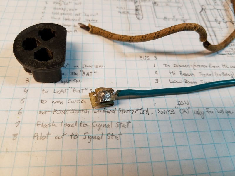
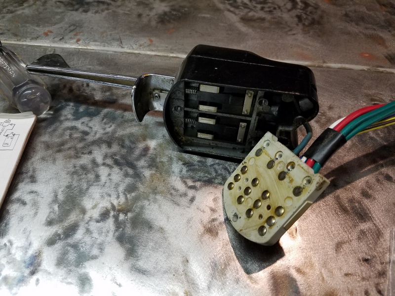
Possible Solution #2: After some thinking, I wondered if it was possible to modify my 900 series unit to be like an 800 series Signal Stat....those units DO act like SPDT switches for both front and back. I popped open the 900 series unit and it turns out it IS possible: The SPDT function for the front circuits is still "baked in" to the 900 series design. If I add a couple contacts and cut some traces, it will work like an 800 series Signal Stat. So that's what I did.
Here's a picture of the 900 series I have. Note the sliders in the unit, and the contacts on the contact plate. If you play with this, you'll see how this clever thing works.
Rather than take ten more paragraphs to explain how it works (and give myself a sharp pain behind my left eye), I'll just explain how I modified the contact plate to add a second input to the front turn signals (making it into a SPDT switch).
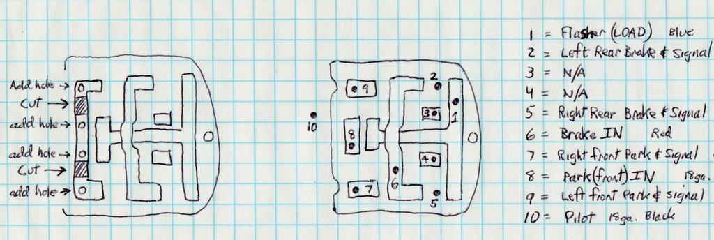
The drawing below shows the "trace" side of the contact plate. The traces are thick copper stampings in the shapes shown. The inputs and outputs are soldered to these plates. The contacts go through the plate and the ends are riveted to hold down the traces at the other side. The version I have has no contacts on the last row even though there are provisions for them. The trace over the absent row of contacts is solid. In the left of the drawing you can see where I drilled holes and cut the trace.
FIrst, drill holes through the trace using the blank holes on the other side as a guide.
I made contacts myself to put into the new holes by using M2.5 brass slotted screws with the heads filed down until the slots disappeared.
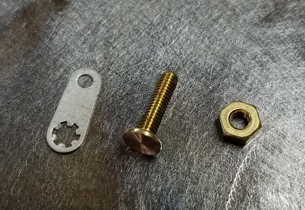
The smooth heads will function as a contact surface. Make sure the head heights fit nicely in the insulating plate. The new contact screws were installed wiith brass nuts. After tightening down the new "contacts", I cut the trace in two places as shown. In the image below, on the lower right of the plate, you can see the new cuts (note too the ground lugs I added for new leads).
The trace is now in three sections: the center section will be the new Parking Lamp input and the outer traces will be outputs that go to the front left lamp and the right front lamp.
The right side of the drawing above shows the new "pinout" of the Signal Stat. Pin #10 is not part of the plate, it's simply the indicator bulb in the unit itself.
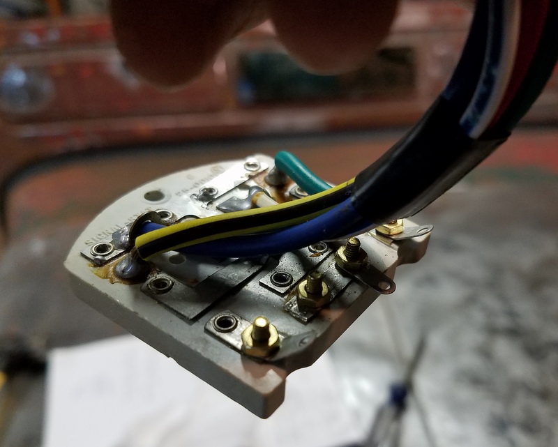
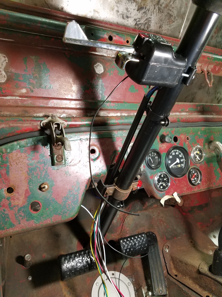
When the unit is mounted to the column, there are a bunch of wires coming out that need to go play with the rest of the harness under the dash. These were rather ugly. To hide them, I made up a tube and welded it to a couple home made clamshell clamps. I ran all the wires to and from the signal stat through the tube to keep it neat. The clamshell simply screws together around the steering column. I grounded the Signal Stat through the slider mounting screw inside the case and ran that wire to a ground lug on the fuse panel. You need to ground the housing to get the indicator bulb to work!
The turn signals work great, and the single filament front parking lamps work like original when the light switch is pulled "one click" out, but "blink" when I use the Signal Stat!
Switches
The original headlamp switch and hi/lo beam switch have little tabs that can be bent open and taken apart which allows them to be carefully cleaned. Yes, I refurbished these switches:
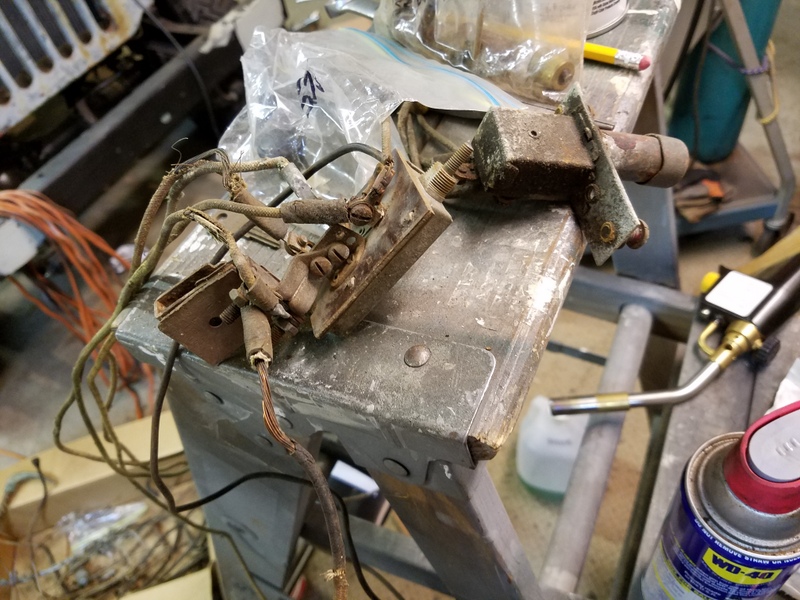
I had good luck blasting the insides of my hi/lo beam switch with sodium bicarbonate (aka baking soda). It's fairly gentle but requires a full cleaning and re-greasing of the innards with dielectric grease. The light switch only needed blasting of the outside.
The ignition switch that came with the Jeep was worn out (it wasn't original anyway) so I bought a universal switch from an auto parts store and it barely lasted for two months. What a piece of junk. I stepped up and got a Cole Hersee M-712-BP switch.
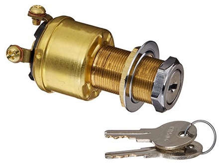
Ya. Much better. It's got a "start" postition so I can use the key engage the starter. I miss the floor starter so I may abandon the "start" position on this switch and wire in a CJ2A electrical floor mounted switch in the place where the mechanical foot switch plunger was.
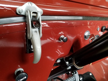
Someone popped out the governor "knockout" plug on my dash leaving a hole. I'd love to find a governor rig for my Jeep, but in the meantime, I stuck in a vintage pull switch that I had laying around. It looks purposeful...macho....awesome....but it doesn't do anything except fill a hole for now.
Horn
This thing still had it's original horn.
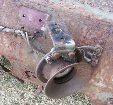
It didn't work, so it was taken apart, cleaned, blasted and painted.
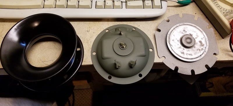
The coil tested okay, so decided to get it working for 12 volts. I figured this would need about a 1 ohm resistor. Rather than a big clunky high current power resistor, I made one using nichrome wire. A few inches of length gave me about 1 ohm resistance, and it can take high current. I insulated it with some ceramic beads (meant for this sort of thing) to insulate it and "take the heat".

The black wire in the center of the picture is the original lead from the coil to the terminal. But note how I spliced in my "resistor" in series with that wire. I curled it around to fit inside the housing.
I put it back together with a paper gasket seal, adjusted the points and it works.
The Rest
After checking that everything worked, I wrapped all the harness sections with non-adhesive harness tape. A smidge of regular eletrical tape at the beginning and a tuck at the end prevents unraveling. You'll never have to contend with goopy residue.
I managed to save just about every original "P" clip from the old harness and refurbished them for re-use in all the stock locations. It looks great.
That's It
Wiring up a vehicle from scratch is a big job. But the point of this section is to show that, just like the rest of the project, if you take one step at a time, it will get done. You'll have a reliable system that you can trust.
To go back to top click here!
SFS
Links:
Willys Jeep CJ3A Forum
There exists a nice set of webpages for CJ3A's. It's got a forum too that caters to both '3A's and CJ3B's. It's a great resource, and frequented by very knowledgible folks.
1967 GTO Original Owner
These two videos feature an original owner GTO. This car was featured in Hemmings Muscle Cars magazine a couple years ago. Part 2 has inside and outside shots of the owner driving the car. Very nicely done.
Blues Maker
"Mississippi" Fred McDowell. One of the great Bluesman. This is a documentary made in 1969.
Pinstripes
Pinstriping the ol' fashioned way. Pretty nice.
MGB Racecar
I've always liked MG's. Watch this MGB lift it's inside tire a few inches off the tarmac when going "'round the bend". Awesome.
Pepsi Throwback

Pepsi has put out a "limited edition Throwback" version of Pepsi with REAL sugar, instead of high fructose corn syrup which has been used since the 80's. Holy cow there IS a difference; it's WAY better. Find some quick!