
Projects:
GTO
My
67 Pontiac GTO
Trunk Body Work
-Trunk pans
-Wheel wells
Body Work Part 1
-Rear Quarters
-Rear Door Jambs
-Window Reveals
Body Work Part 2
-Cowl
-Pillar
-Rocker
Body Work Part 3
-Windshield channel
-Doors
-Fenders
GTO Paint
-Filler work
-Priming
-Blocking
GTO Frame Work
GTO Convertible Top Pt 1
-Top Frame
GTO Convertible Top Pt 2
-Top Trim
GTO Drivetrain
-Engine
-Quadrajet Rebuild
-Exhaust
-Axle
Muncie
Rebuild
popular
Auto to Manual Swap
1967
Ram Air GTO
story
Wheelhouse Filler template PDF
Willys CJ3A
CJ3A Intro
Engine and REBUILD
Drivetrain
BodyWork 1
BodyWork 2
BodyWork 3
BodyWork 4
Paintwork 1
Paintwork 2
Final Assembly
Final Assembly 2
Electrical System
Other Rods
TJ Wrangler Rubicon
CJ7
CJ8
Decrepid Dakota
Powerdyne Minibike
Allis Chalmers B engine rebuild Part 1
Allis Chalmers B engine rebuild Part 2
Allis Chalmers Generator to Alternator conversion
Gizmos
Stereo camera
rig
Stereo mic preamp
About:

Feeds

Markup
1967 Pontiac GTO Convertible Top Installation Part 1
This page deals with the installation of a convertible top on a 1967 GTO. Part 1 deals with restoring the top frame assembly.
To see the top trim installation, go to Part 2.
October 27, 2013
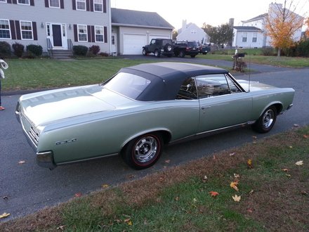
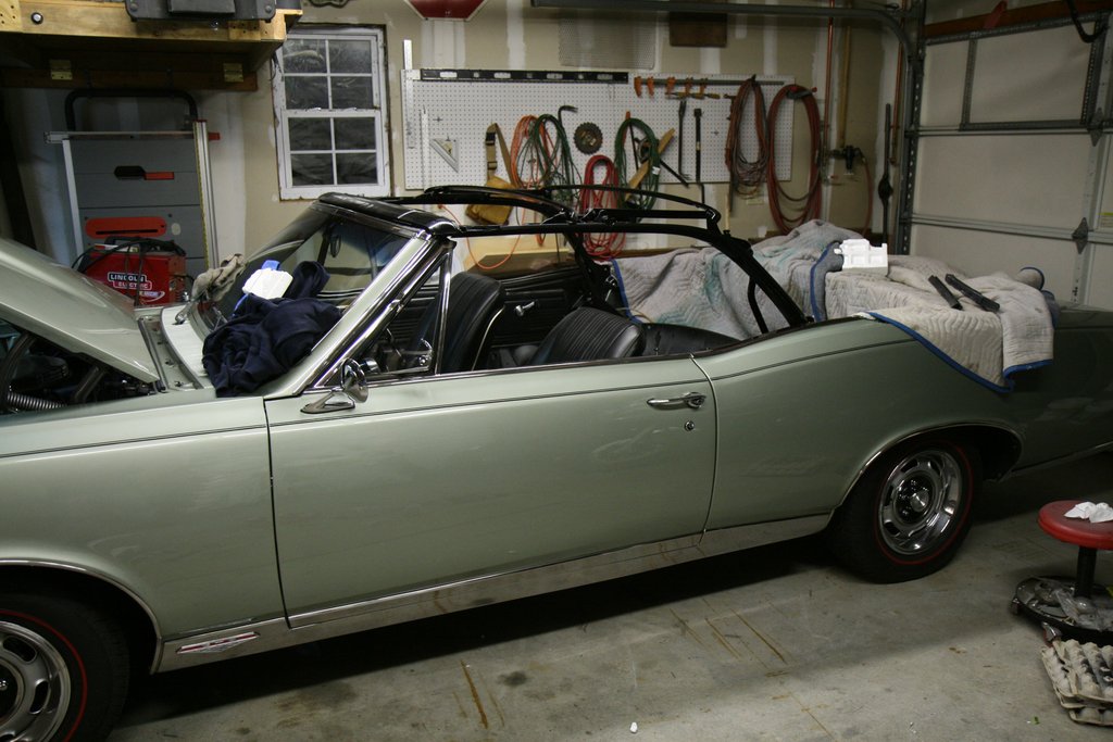
One of the last tasks to be done on the GTO is the installation of a new convertible top. In keeping with the effort on the rest of the car, the top frame will be taken apart for repair, cleaning and a repaint. Then it will be time to install new pads, window, top trim and weatherstripping.
This entry is detailed and meant to help folks who are thinking of taking on a job like this themselves. You may want to skip this entry unless you like this kind of detail!
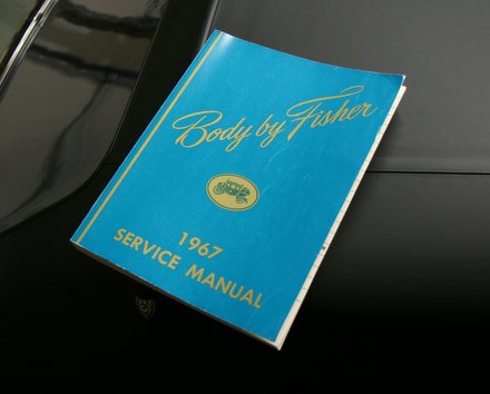
Since I've never done this sort of work before, I scanned the internet for convertible top installations. There's a fair amount of info to be found, and some of it is useful, but alot of it is fragmentary and no single source was very comprehensive. I ended up relying on the 1967 Fisher Body manual for the most part. I found that it had the most detail, loads of illustrations, and it featured alignment and troubleshooting guides. The alignment instructions are perfect for installers like me with no old top to use as a reference. The 67 Fisher Body manual I used is a nice quality reprint.
Convertible Top Frame Resto
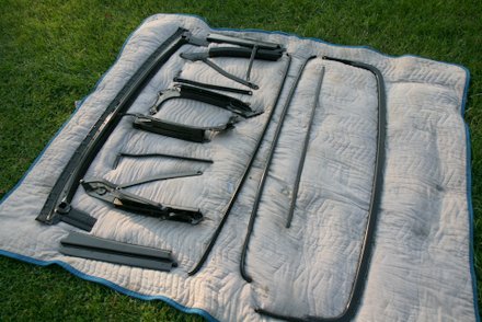
Early on in my ownership of the GTO, I managed to acquire another top frame, so I was fortunate to have two top frames to pick and choose the best bits and pieces from. Besides some rust on the sheet metal parts, the frames were in excellent shape. Still, they needed to be disassembled for full detailing.
Most hinge points come apart after removing the hardware. There are scads of bushings, washers and shoulder screws, and even some set screws. Some joints are permanently riveted and I left those alone.
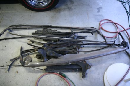
The top frame is a machine of sorts, with quite a few parts, so I took lots of pictures and carefully tagged and bagged.
Header Rail Repair
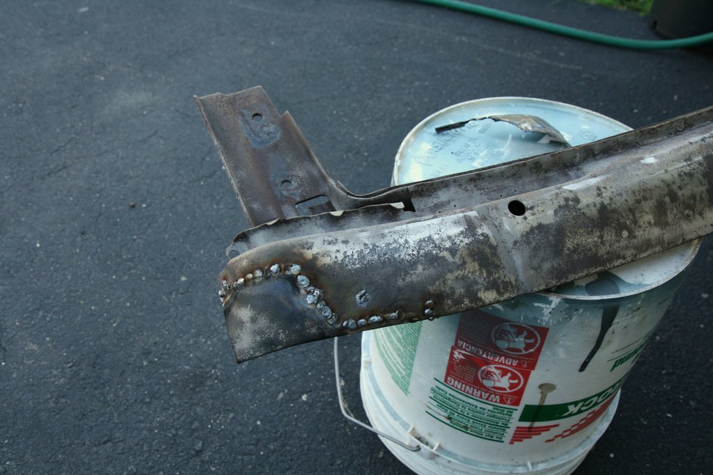
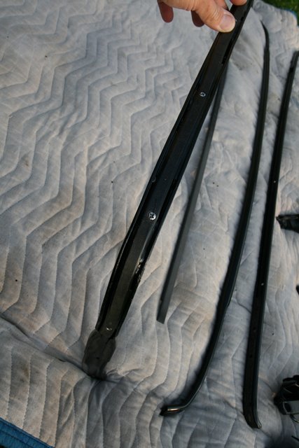
The only part really needing repair was the header rail. This piece is made up of stamped and welded sheet metal pieces and of course they were never painted on the insides, so they suffered from rust. I was able to cut patches from one to weld into the better one. The unit was then coated with paint inside and out.
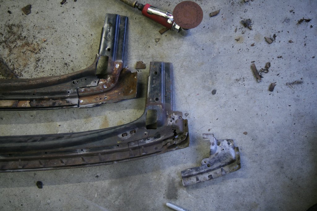
The patch above was a cut and paste, but some repair required breaking out the body hammers and fabbing up some new metal.
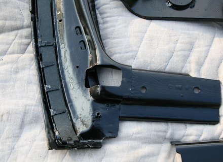
The best parts were selected and painted.
Tacking Material
These top frames used hard, solid cardboard as a tacking material for the staples, and after 45 years, it all definitely needed replacement. New "modern" plastic/rubber type tacking material was procured from Topsdown.com. The header rail uses a wide tack strip that's about a 1/4" thick. The new stuff was trimmed a bit in width and stuck down onto the recess with some rubber adhesive. Note the metal tabs that are also used. These fold down over the tack strip. I slathered the paint on rather thick where the frame will not show.
Other parts of the top frame utilize 1/2" width strips with a 3/8" thickness. The top side of the header needs one layer of this stuff for the top pads on each side. The original tacking stuff was retained with tabs and huge staples shot into the metal. I used stainless steel oval head sheet metal screws to replace the staples. Click the picture below to see the screws.
The rear bow required stacking two 3/8" thick strips to fill the deep channel. The thickness was not exact, so I used a beltsander to sand it to the correct height. The sanding also scuffed up the material so it would adhere better.
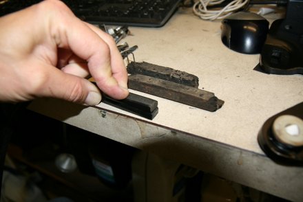
Adhesive and more stainless screws were used to bond the new tacking material "stack" into the deep channel of the rear bow:
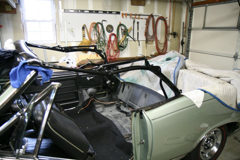
The refurbished top frame parts were assembled and installed into the car along with the original pump and rams assembly. As far as I know, it's got the original Type "A" fluid in there.
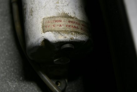
Type A hydraulic fluid was one of the first automatic transmission formulations, and up until the early 70's utilized whale oil as an ingredient.
The top frame was installed while folded, then it was extended and the bows were installed.
The first and second bow hardware was reused, consisting of chrome oval head machine screws with star washers. I slathered them with thread locking compound because there aren't many threads in the bows for the screws to grab. Some frames might have rubber shims on each side of the first bow, so I reinstalled the units my car came with. They're sitting on top in the picture below.
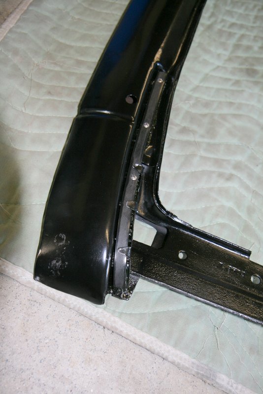
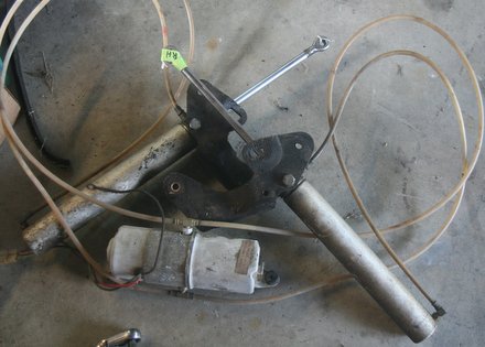
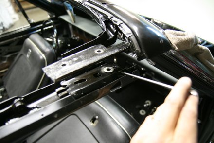
Male Hinges
The top frame is attached to the body of the car with something GM calls "male hinges". Here's a shot of the male hinges (in black) with the rams attached.
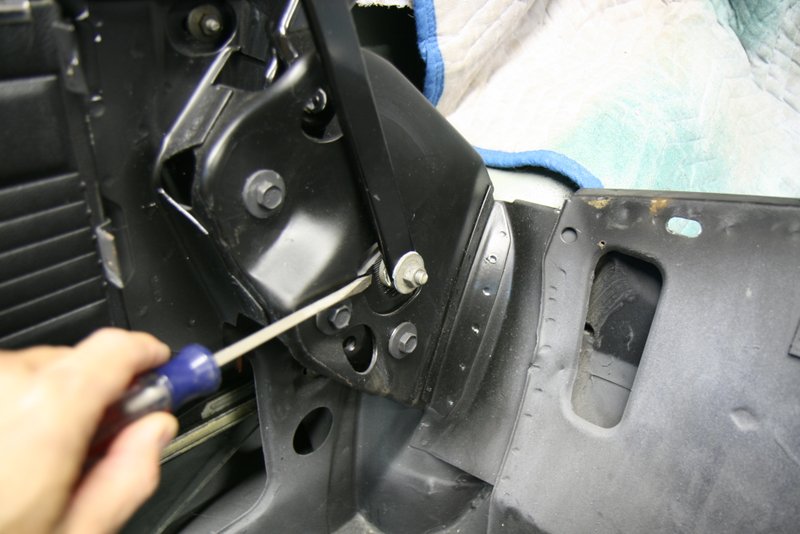
The holes in the car are oversized to allow adjustment of the hinges. As seen below, the hinge is obscured by the bracketry of the car body, and two of the male hinge bolts are surrounded by tape which I was using for alignment reference.

The male hinge adjustment allows you to set the top frame height to a proper gap over the side windows. In addition to height adjustability, the male hinge can be rotated slightly forward or backward which dictates how well the folded frame sits within the well. Proper adjustment allows the top frame to fold up nicely inside the well without sticking up.
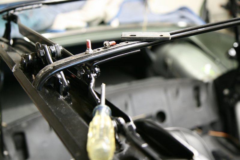
Control Link
When the top frame is put "up", it needs to be fully unfolded so there is no sag in the frame when the header rail contacts the windshield header. This adjustment is made with the control link. There is a serrated bolt at the bottom of the link that allows the link to be adjusted vertically. A small adjustment has a big impact on how the top frame unfolds.
I set the control link so that the top is unfolded completely when the header rail is about six inches away from the windshield. Below you can see how the frame is properly aligned and the curve of the frame is just right when the frame contacts the windshield header.
One more adjustment point is the header rail itself which can be adjusted fore/aft to meet up nicely with the windshield header. I got a little "custom" here by adding a washer to cant the header a bit so the side glass would meet up better with the weatherstripping.
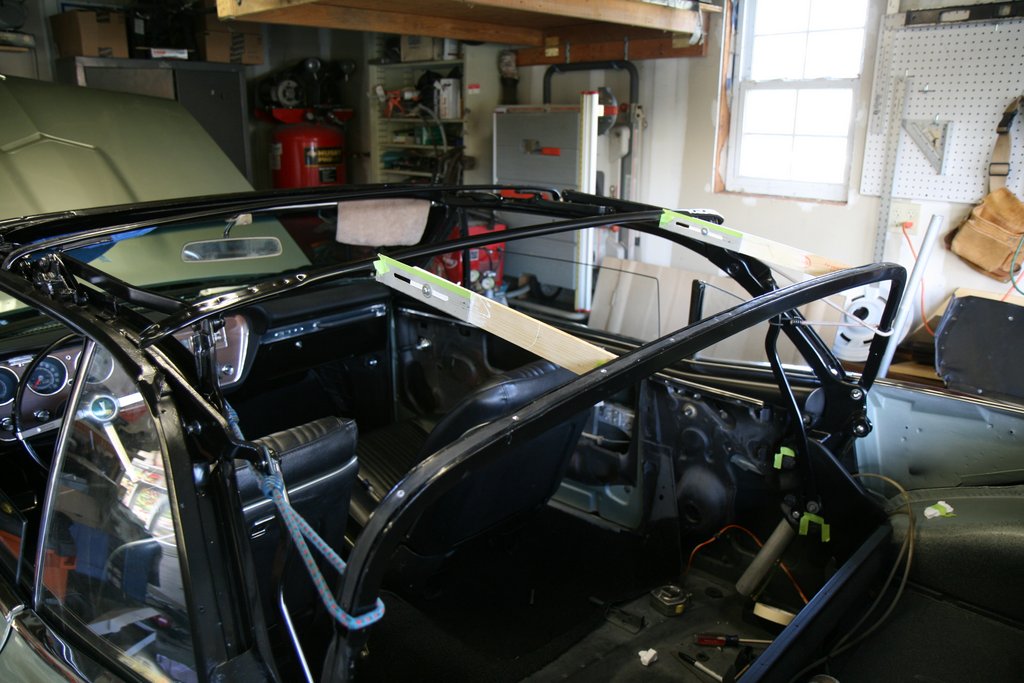
Rear Bow Alignment
The rear bow must be placed in a specific position when the top trim is installed in order for tack points and listing pockets to line up correctly. This is known as setting the "bow height". The bow height is measured from the rear edge of the rear bow down to the front edge of the stainless well trim.
The Fisher manual describes temporarily installing spacer sticks to set and maintain the bow height during top trim installation. These sticks are set between the rear bow and the center bow.The distance between center and rear bow should be 15.25 inches for this car. With the sticks in place, the rear bow should now be 22 inches to the edge of the well trim.
Note the bungee cords used to pull the rear bow against the spacer sticks.
Rear Well Pinchweld Trim Mod
Before starting on the top trim installation I addressed a fit problem with the pinchweld stainless trim around the well.
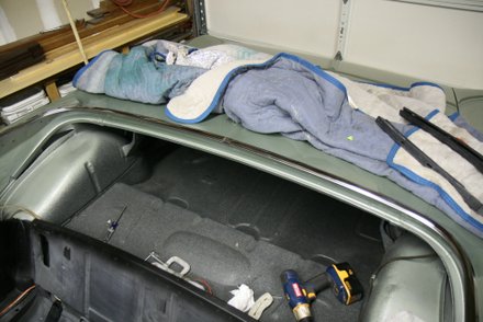
In all the time I've owned this car, the well trim would not stay put. It slipped off the pinchweld in the center area. When I test fit my new top boot, the boot clips tugged on the trim and it would partially pull off.
The solution was to install a screw where the two pieces of trim meet in the center. Luckily, the passenger side pinchweld trim overlaps the driver side trim where they meet in the center, so it's a good place for a hidden screw.
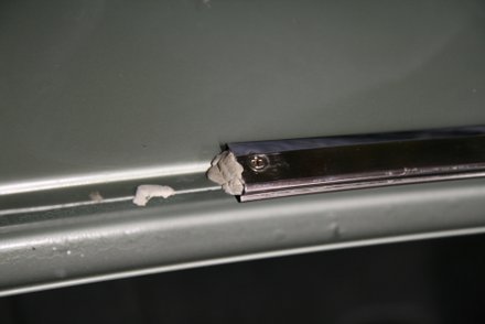
The passenger trim was removed, and the driver side trim partially pulled off. A hole was drilled in the driver side piece, and a countersink shape was formed into the trim so a flathead screw would sit flush.
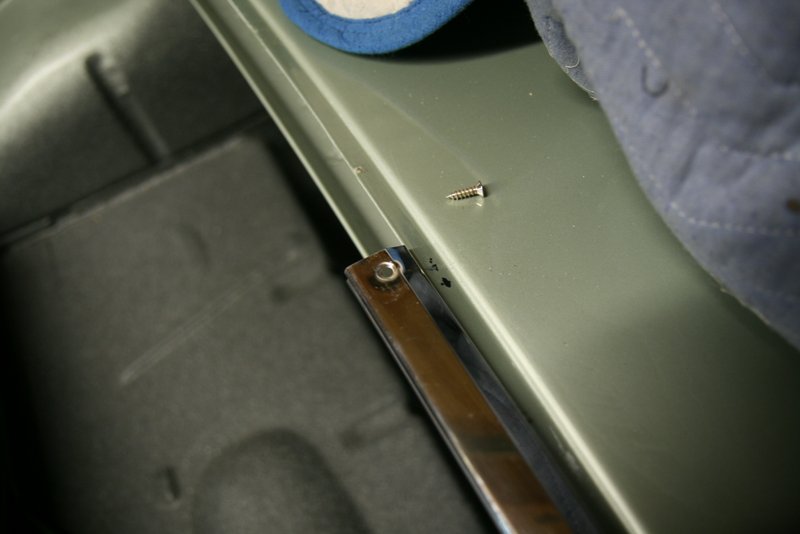
The pinchweld was carefully drilled and the screw driven in. I used a bunch of putty just to seal it up. The screw was just long enough to grab the pinchweld.
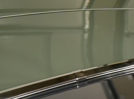
The passenger side trim envelopes the driver side trim end when it is pushed on and stays in place too. The trim is nice and tight now all the way around.
The top frame is on, aligned nicely, and it goes up and down smoothly. It's now ready for installation of the top trim.
Click here to go to Part 2 of the Top Installation.
SFS
Links:
Willys Jeep CJ3A Forum
There exists a nice set of webpages for CJ3A's. It's got a forum too that caters to both '3A's and CJ3B's. It's a great resource, and frequented by very knowledgible folks.
1967 GTO Original Owner
These two videos feature an original owner GTO. This car was featured in Hemmings Muscle Cars magazine a couple years ago. Part 2 has inside and outside shots of the owner driving the car. Very nicely done.
Blues Maker
"Mississippi" Fred McDowell. One of the great Bluesman. This is a documentary made in 1969.
Pinstripes
Pinstriping the ol' fashioned way. Pretty nice.
MGB Racecar
I've always liked MG's. Watch this MGB lift it's inside tire a few inches off the tarmac when going "'round the bend". Awesome.
Pepsi Throwback

Pepsi has put out a "limited edition Throwback" version of Pepsi with REAL sugar, instead of high fructose corn syrup which has been used since the 80's. Holy cow there IS a difference; it's WAY better. Find some quick!