

Projects:
GTO
My
67 Pontiac GTO
Trunk Body Work
-Trunk pans
-Wheel wells
Body Work Part 1
-Rear Quarters
-Rear Door Jambs
-Window Reveals
Body Work Part 2
-Cowl
-Pillar
-Rocker
Body Work Part 3
-Windshield channel
-Doors
-Fenders
GTO Paint
-Filler work
-Priming
-Blocking
GTO Frame Work
GTO Convertible Top Pt 1
-Top Frame
GTO Convertible Top Pt 2
-Top Trim
GTO Drivetrain
-Engine
-Quadrajet Rebuild
-Exhaust
-Axle
Muncie
Rebuild
popular
Auto to Manual Swap
1967
Ram Air GTO
story
Wheelhouse Filler template PDF
Willys CJ3A
CJ3A Intro
Engine and REBUILD
Drivetrain
BodyWork 1
BodyWork 2
BodyWork 3
BodyWork 4
Paintwork 1
Paintwork 2
Final Assembly
Final Assembly 2
Electrical System
Other Rods
TJ Wrangler Rubicon
CJ7
CJ8
Decrepid Dakota
Powerdyne Minibike
Allis Chalmers B engine rebuild Part 1
Allis Chalmers B engine rebuild Part 2
Allis Chalmers Generator to Alternator conversion
Gizmos
Stereo camera
rig
Stereo mic preamp
About:

Feeds

Markup
Op Amp Based Microphone Preamplifier
August 20, 2009
I like fiddling with electronics. I also like really good sounding audio recordings. A few years ago, I found out about binaural audio recordings. A binaural recording can be made by arranging two microphones in a dummy head with dummy ears. The shape of the head and ears sonically give a sense of space that our brains use to get a sense of direction. Typical stereo music recordings are artificially separated into two channels by sound engineers and any directional sense is destroyed.
Well, I'm not going to make a wig head with microphone ears, but I still want to make my own stereo-ish/binaural-ish field recordings. I found out that the Sony MD (Minidisc) players/recorders of a decade ago (pre-MP3 player days) were useful for field recording, but they suffered from crappy microphone inputs. However, many of these recorders came with Line Inputs which allows the use of preamps. A very cheap and simple preamplifier can be made with just a little dough using an operational amplifer, some capacitors and resistors. Of course, it's only cheap if you make it yourself. And that's half the fun.
Research
I've got pretty much no business messing with electronics, but with the internet at your disposal, you can essentially find out how to do anything, like making mic preamps. There are some good folks out there who really know their stuff and they're nice enough to share, some even with step by step instructions.
I had made a mic preamp a few years ago with vectorboard but it was big and bulky because the jacks and potentiometers were all mounted away from the board, and this meant lots of wires. I used a TI T082 opamp and microphone elements all from RadioShack. The circuit used a single 9V battery with a requisite voltage divider.
Despite the big ugly enclosure and Radio Shack parts, it worked very well and the high gain gave me some great recordings. But I wondered if I could get a lower noise floor with better capacitors, better mic elements and a dual battery supply. I also wanted a smaller housing.
After checking out a few websites, I decided to stay with the basic opamp design. I discovered a cool mod that can be performed to electret microphone capsules some call the "Linkwitz Mod"; a mod that allegedly makes the elements a bit quieter (lower noise) as well as being capable of higher sound pressure levels (SPLs). This mod reverses the mic polarity which requires changes to the circuit. The Linkwitz mod is well documented here at Linkwitz Labs and the author does give credit to a colleague for the original idea.
Since I still have a set of non-modified microphones, I decided to incorporate a mic polarity switch to allow me to use either set of microphones. A dual rail supply (two 9V batteries in series) allows me to keep the mic input jack ground the same for modified and non modified mics. I got the idea for the polarity switch from subatomicglue.com, although the author did not use a dual battery supply.
I wanted this all to fit all this into a small package, such as a nifty Altoids tin. I found no layout small enough to fit into an Altoids tin, or even a circuit with a dual battery supply, so I had to design the board myself.
The Circuit Layout
There are a few free PCB design software packages out there and I selected one called Eagle Layout Editor. Learning to use this software became a project in itself, but I found a couple really good tutorials. See links below.
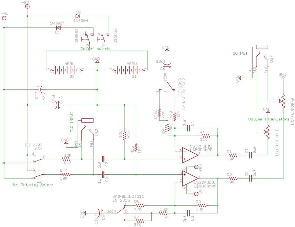
The schematic I came up with is mostly based on a couple opamp preamp designs out there, but I had to figure out the dual battery scheme. I did run this by a friend who happens to be a professional in electronics and he gave it his blessing.
The board I finally came up with looks like this:
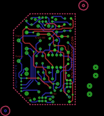
I decided to go nutty and make a two sided board. Making a homemade two sided board can get tricky; you have to align the masks very closely so that the pads and vias match up. But making some fiducials helps with aligning the two masks before you iron them onto the board.
The circuit is based on classic opamp amplifer design. But some features have been added:
A gain select switch
A polarity switch for the input mics (as mentioned above)
A "volume" pot for output levels. It actually functions as an output attenuator
An On/Off switch.
Also added some "vias", or pads, in order to solder on an LED lamp to indicate "ON".
To fit these all on a small board, I used a family of slide switches that the author at subatomicglue.com used. These are E*Switch Brand "EG" series switches. Small little boogers.
I used a Panasonic dual gang 10K pot for the output volume. This is a nice pot to use because it's small, it has two channels for stereo, and it was fairly cheap. I bought a cool knob for it too.
So integrating these into the board layout entails downloading the datasheets, creating footprints in Eagle Layout software, then putting them into the circuit. It's a load of work. Kinda fun, but after many hours you wonder why you do this to yourself.
After agonizing over the trace routing, things looked good enough to proceed.
Etching the Circuit Board
When Radio Shack closed a bunch of stores a while back, I swooped in and bought a bunch of stuff for really cheap. This included a board etch kit. The kit is basically a copper clad electronic board with ferric chloride solution to etch the copper. The kit includes a Sharpie pen to draw the traces, and the ink acts as a cover (or "mask") to keep the ferric chloride from etching away your intended copper traces.
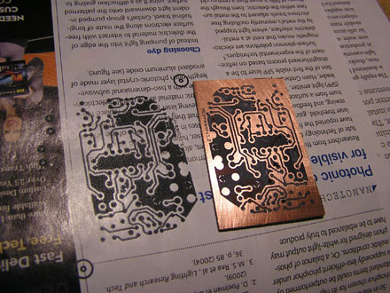
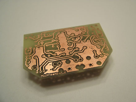
Instead of tyring to hand draw traces, I found this cool technique which involves making a "mask" from a laser printer. The toner from the printer is powdered plastic and the print process melts the words and images onto the paper. If you print to certain types of semi-glossy magazine paper, you can lay the paper onto your copper board (toner side down) and re-melt the toner onto the copper using a clothes iron. The paper can then be disolved away with tap water, leaving the toner. The above image is of the bottom traces. The mask to the left is an extra print.
I've made a couple of boards with this technique and the resolution is quite impressive. Many electronics projects in magazines and even websites will give you images that you can just go and print, and you're ready to iron on and etch.
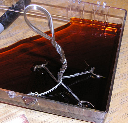
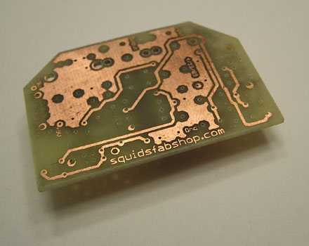
Etching took less than 10 minutes. No more unwanted copper:

You can see the protective plastic mask is still there, and you can even see the light showing through the board giving a hint of the top layer on the other side.
Some lacquer thinner takes the toner right off.
After cleaning the toner off, I trimmed the board to size. I was able to use a CNC machine to perform all the drilling. There are over 110 holes of 3 different sizes. The drill bit wandered a bit on a few, but no worries.
Stuffing the board
June 2009
I placed a few components on the board and all seemed well enough. But when the real "stuffing" began, things started to get interesting.
Since I had no "instructions", I just started to add components that seemed to make sense to put in first. But after a few components were added, I noticed I forgot to solder some of the feedthroughs. The feedthroughs were simply pieces of wire soldered top and bottom of the board. I relied on these especially for the grounds. So, out came the solder sucker to remove the parts in order to access the via holes/feedthroughs.
When I added the switches, I noticed that the housings came all the way down to the surface of the board. I misinterpreted the data sheets regarding the housings. And, unfortunately, there was a place where the gain switch housing was contacting a top trace. The pic below shows the housing contacting the trace.
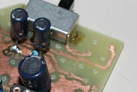
So I cut the trace and soldered on a piece of wire-wrap wire as a jumper. I've since corrected the circuit layout so that the traces avoid the switch housings. Below you can see some blue wire wrap wire I used to patch the cut trace.
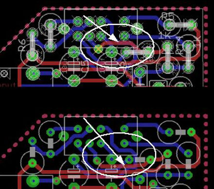
The image below is of the layout generated by the EAGLE PCB software with my fix incorporated: The top section shows the conflict area in question on first version board I made, and the bottom shows the revised board layout with the revised trace placement. Incidentally, with this layout software, the top traces are in red, and the bottom traces are in blue. The green circles are vias and pads.
Finishing up
July 1, 2009
The project started to drag on due to some distractions with other projects. One last push to get this thing operational. I finished stuffing the board and finally was able to fire it up. I put in a 8DIP socket so I could swap in various opamps I had. On my previous circuit, I used a Radio Shack-sourced opamp, the TL082CP. For this project, I plugged in a BurrBrown OPA2132A I had lying around from a headphone amp project I never built.
When I first turned it on, it didn't work at all. Oh jeez. I dreaded the thought of going through the packed circuit trace by trace. I started by checking the power supply traces and then the grounds. Woot! I found a missing solder joint that connected a ground on the bottom of the board. A quick soldering and all is well. With that done, it was time to get the board into a package.
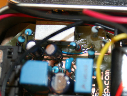
Since I wanted to get it usable for a looming trip, I allowed my standards to slip in order to get it packaged quick. I still wanted to do a slick job with an Altoids tin, but jeez, working with lousy thin sheet steel is a challenge. I'll tackle the nuances of working with Altoid tins at some later time. I stopped caring about looks and just hacked it up to get the board into a box. I had 2 evenings left to do it.
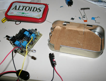
Cardboard liner to keep the board from shorting out. Eh.
The Mics
My first mic amp rig from a few years ago used a stereo microphone rig that utilizes cheapie radio shack mics (which actually sound pretty darn good to my untrained ears). In the quest for knowledge, I wanted to try "Linkwitz Modded" mics. I purchased some WM-61 Panasonic mics from Digikey and performed the trace cutting and re-soldering as per the instructions found on the Linkwitz website.
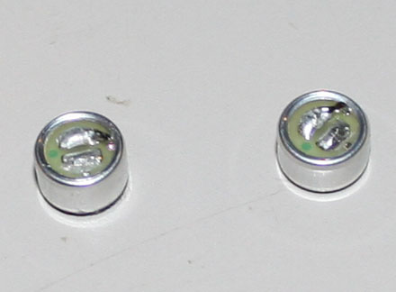
The electret mics have two pads on the backside. One pad has a trace that runs to the side to a case ground under the lip of the package. The other pad has no traces running off to the sides. The mod involves cutting the trace going to the grounded pad, and then connecting the other pad (I'll call it the "island" pad) to case ground. Contrary to what I've read, I was able to perform the connection mod to the "island" pad without any trimming or shaving of the housing. There is a ground trace that sticks out and this can be soldered to the floating island pad. The difficulty is the small size of the mic element and trying to solder to the tiny traces. A good quality small tipped soldering iron is a big help.
In the picture below, both elements are shown with the "cut trace pads" facing down in the image. You can just make out the trace next to the housing on the bottom of the right element. On both, you can see the top pads with the small piece of solder coated wire running off to a small trace peeking out on the right side.
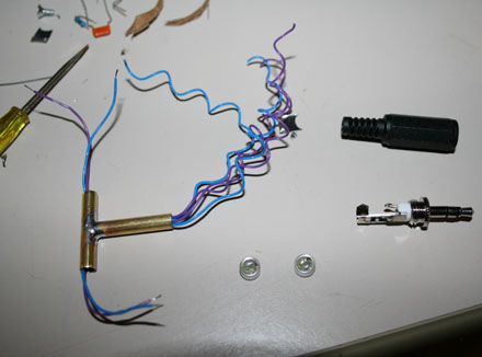
Once done, I made up a "T" with some brass tubing and ran some wires through it, then soldered up the jack and the modded mic elements. In keeping with the pocket size theme, I made the mic wand small so it would simply stick out of the preamp case. Too small to be binaural, and not the greatest stereo separation, but nice for convenience.
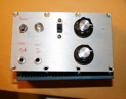
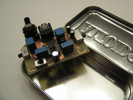
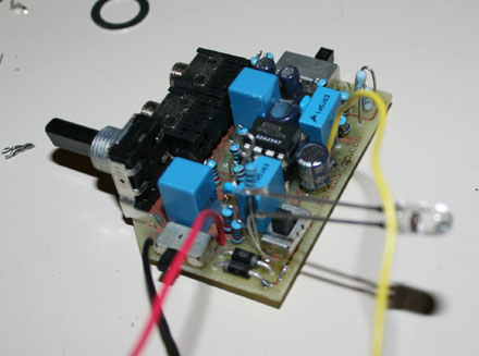
Here is the completed "Engineering Model" of the Microphone Preamplifier. I managed to get it all into the tin.
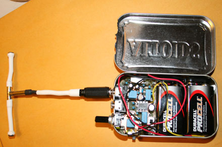
I managed to get it all into the tin.
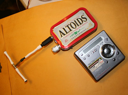
Here's the packaged amp alongside my MD recorder. Simply run a cable from the output of the mic preamp to the INPUT socket of the recorder.
Parts List
| ID | Size | Mfr | P/N | |
| R1 | 100 ohm | Resistor | ||
| R2 | 100 ohm | |||
| R3 | 33 kohm | |||
| R4 | 33 kohm | |||
| R5 | 470 ohm | |||
| R6 | 1.5 kohm | |||
| R7 | 27 kohm | |||
| R9 | 1.5 kohm | |||
| R10 | 27 kohm | |||
| R12 | 10 kohm | |||
| R13 | 10 kohm | |||
| R14 | 470 ohm | |||
| R15 | 10 kohm | |||
| R16 | 10 kohm | |||
| C1 | 2 uf | EPCOS | B32529D0225J | |
| C2 | 2 uf | EPCOS | B32529D0225J | |
| C3 | 2 pf | Murata | RPE5C1H2R0C2P1B03B | |
| C4 | 2 pf | Murata | RPE5C1H2R0C2P1B03B | |
| C5 | 10 uf | Panasonic | ECE-A1CKG100 | |
| C6 | 10 uf | Panasonic | ECE-A1CKG100 | |
| C7 | 1 uf | EPCOS | B32520C155J | |
| C8 | 1 uf | EPCOS | B32520C155J | |
| C12 | 47 uf | Panasonic | ECE-A1CKG470 | |
| C13 | 47 uf | Panasonic | ECE-A1CKG470 | |
| Mic | Panasonic | WM-61 | ||
| D1 | diode | 1N4004 | ||
| D2 | diode | 1N4004 | ||
| Switch G1-G2 | Gain | E-switch | EG-2315 | |
| Switch U4 | Polarity | E-switch | EG-2207 | |
| Jack U2 | Input | CUIAudio | SJ1-3543 | |
| Jack U3 | Output | CUIAudio | SJ1-3543 | |
| Switch U6 | On/Off | E-switch | EG-2211 | |
| 10K Audio Pot | Attenuator | Panasonic | EVJC20-A |
I purchased a metal film resistor kit from ebay.
Everything else was sourced from Digikey.
The Epcos capacitors are metalized polyester film caps. These are more accurate than general electrolytics and this helps when trying to match your stereo channels.
The published values for the capacitors versus what I used might be a bit off, but the part numbers I show are the ones I used.
Summary
I got a little ambitious with this project by teaching myself how to use a PCB layout software and designing the physical circuit layout myself. This required a lot more time than I really wanted to, but I stuck with it and I'm happy I got it finished.After assembly and a few minutes of troubleshooting, the circuit worked nicely.
Compared to my first mic preamp, this circuit seems to have lower gain. I can't comment yet on whether this circuit has less noise than my first simple circuit. I hope to do some measurements.
The main objective was achieved however; making a smaller circuit in a smaller case. It's much easier to use.
Sounds
When the weather turns cold, I'll convert all my stuff to digital and I'll post some samples....stay tuned...
Links
Subatomicglue.com This site features one version of a mic preamp
Simple mic preamp This is a great basic opamp amplifer; this is the circuit I used for my first mic preamp
Dal Wheeler method for making PCBs
Digikey A source for all things electronic
SFS
Links:
Willys Jeep CJ3A Forum
There exists a nice set of webpages for CJ3A's. It's got a forum too that caters to both '3A's and CJ3B's. It's a great resource, and frequented by very knowledgible folks.
1967 GTO Original Owner
These two videos feature an original owner GTO. This car was featured in Hemmings Muscle Cars magazine a couple years ago. Part 2 has inside and outside shots of the owner driving the car. Very nicely done.
Blues Maker
"Mississippi" Fred McDowell. One of the great Bluesman. This is a documentary made in 1969.
Pinstripes
Pinstriping the ol' fashioned way. Pretty nice.
MGB Racecar
I've always liked MG's. Watch this MGB lift it's inside tire a few inches off the tarmac when going "'round the bend". Awesome.
Pepsi Throwback

Pepsi has put out a "limited edition Throwback" version of Pepsi with REAL sugar, instead of high fructose corn syrup which has been used since the 80's. Holy cow there IS a difference; it's WAY better. Find some quick!