In
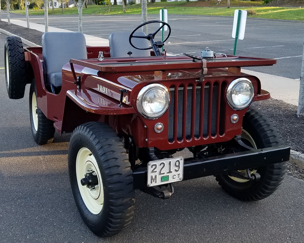
2009, I found an ad for a good candidate replacement Go Devil L134 that was pretty local to me. I went
for a visit and found the seller to be a young fellow with a serious
Willys Jeep affliction. He had Jeeps, engines and parts all over the
woods in his backyard.
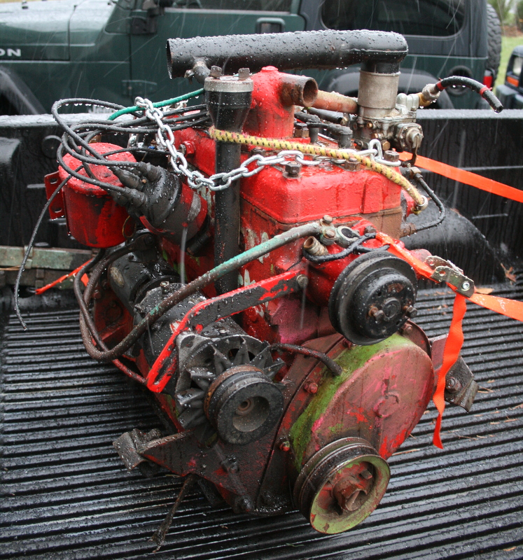
He
used a pine tree as his engine
hoist and the engine I was interested was hanging in the tree. I was a
little hesitant about buying an engine hanging in a tree, but then the
dad meandered over and started throwing in extra parts in order to make
the sale. I think he mostly wanted to clean up his backyard. So, with
an exhaust, generators, and springs thrown into the deal, I bought it.
The engine has a casting
number of 641087, but curiously the last 4 digits were ground off and
then stamped with the "1087" And the stamps look old. The engine
was promptly put away in a corner while I worked on other projects, and
years have passed.
But recently, the Jeep
whisperings have been bubbling to the surface of my brain, and a window
of time has opened up at Squids Fab Shop. It was time to get busy on
the Jeep. I had
never
test run the engine, and I wanted to hear it run, so the
engine was pulled out from it's dusty corner to begin work.
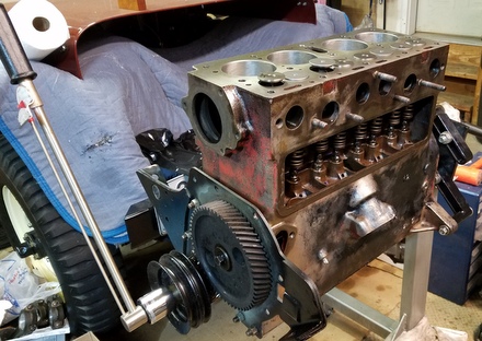
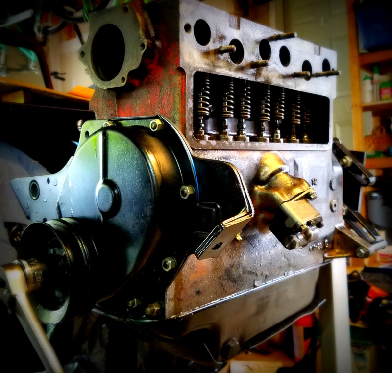
A
crude engine stand was my first mission. A cart was
fashioned with some lumber and casters. Old scrap steel was employed to
adapt the motor mounts and bellhousing to the cart. More scrap steel
was used to position the CJ radiator and shroud in front of the engine
to take advantage of the cooling fan. A small panel was made to hold
water and oil gauges,
as well as switches for the ignition and charging system (not shown
yet.) Note how previous owner did some custom stenciling on the side of
the block. Also note the head is not the same....keep reading below....
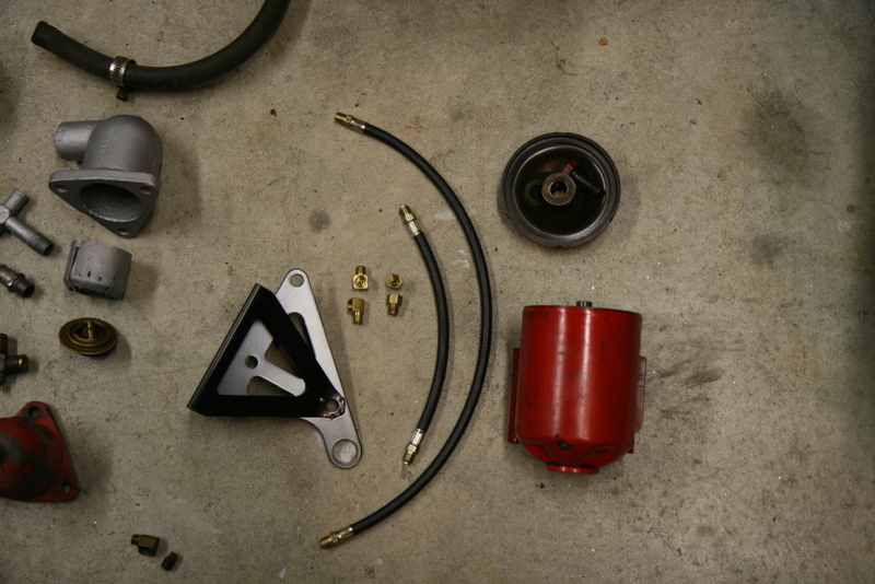
Bypass Oil Filter System
With the "stand" ready,
the engine systems were next: The old
Jeep flathead engines (like many engines in those days) used externally
mounted oil filters, and I was missing many parts. I sourced the
external oil lines from 4wd.com, but saved some dough by getting the
hard-to-find flare fittings at a local hydraulic supply company. (It
pays to search around...there can be huge variations in costs across
suppliers, both local and online.
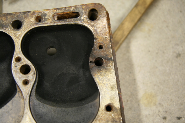
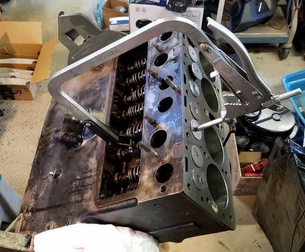
Installing a new oil
filter mount disturbed a few of the head studs/nuts, necessatating a
re-torquing. Unfortunately one of the head studs broke while
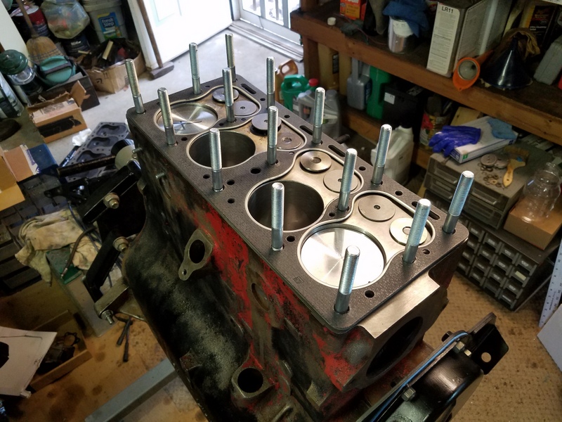
approaching the torque value. So off came the head in order to drill
out the offending stud. While certainly a bummer, it did allow an
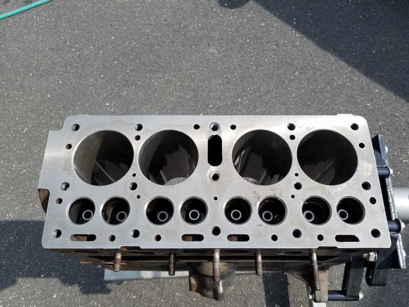
inspection of the pistons, cylinder walls and valves. The good news is
that it's in pretty decent shape and in fact still has standard bore
pistons.
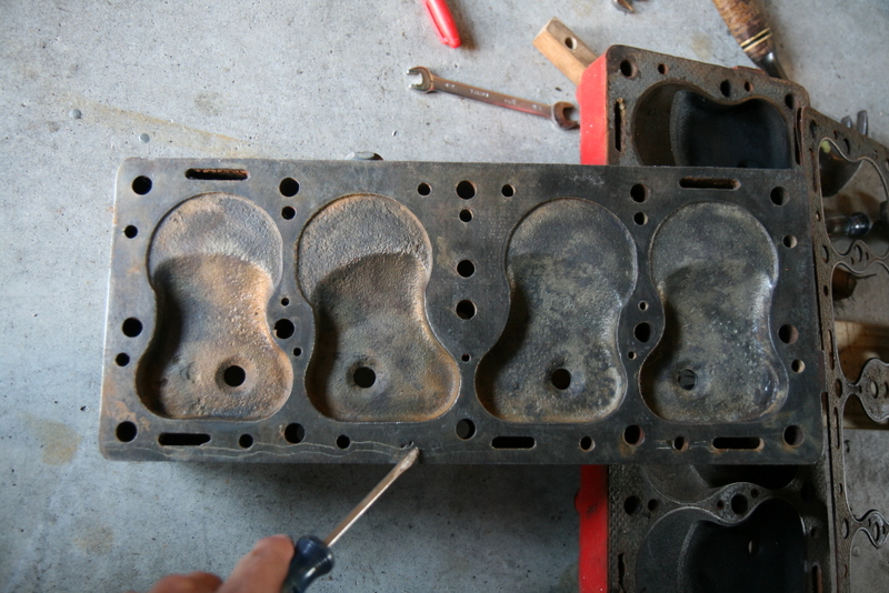
It seems that a crack in
the head gasket allowed gases to erode the stud which weakened it. I
managed to drill out and remove the stud without damaging the original
threads in the block. I sourced some Dorman head studs p/n 675-013 from
Amazon (sometimes you can get Dorman stuff on Amazon for extremely good
prices...woot) and switched to my blasted and cleaned "INDUSTRIAL" head
from the seized engine that came in the Jeep. (The head I removed was
riddled with cracks). I also inspected the tappets, and removed the
intake exhaust manifold which in turn required me to source new
manifold studs. I got those, shockingly enough, on a twirly rack at a
Pepboys.
Charging System
The original CJ Willys charging system was a 6 volt generator
with an external regulator. The components on the Jeep have long been
dormant and likely corroded beyond usefulness so I decided to "upgrade"
to a modern (well, 80's vintage) Delco 12si 3 wire alternator.
The
Delco alternator has internally regulated 12V output, it's cheap, super
reliable, and easy to use. The 12si is probably the ultimate unit to
look for (better internal cooling according to my research), but the
10si's are fine as well. The P/N I sourced is for a 1980 Camaro
application.
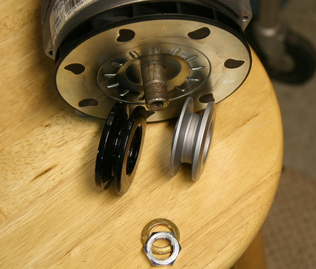
A
minor glitch when using a modern alternator is the
relatively narrow pulley that does not work well with
the
very wide "V" belt the L134 crank and waterpump use. There are
suppliers that sell wide "tractor" type pulleys, or you can
chuck the narrow pulley in a lathe and machine the "V" groove
wider.
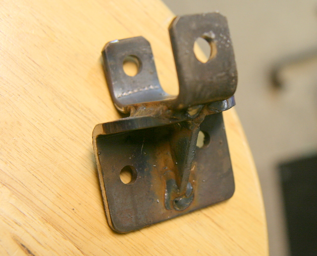
Adapting a modern
alternator to the little flathead requires a custom
bracket which can be had from some Jeep specialists online, but it's
easy to fabricate your own. My little box of scrap metal yielded enough
bits and pieces to weld one up. It's fairly thick steel so I used a
propane torch to preheat the metal for better penetration.
Last
thing to do was to replace the cap, rotor and ignition wires. I figured
the rest should be okay since it was advertised as running when I
bought it. At the first start attempt, cranking speed was normal, but
there was no sign of a pop. A test for spark (with a removed spark
plug) was positive, but there was no ignition when installed. I put in
a new coil, and still nothing. I replaced the points, and bingo!
Instant ignition. A few leaks were attended to, and a few minutes of
run time indicated a dirty carburetor. The solex carb has a bunch of
plugs and caps that can be removed to access internal passages. I
removed all of them and blasted everything I could with carb spray
cleaner. A dramatic improvement to idle quality was observed and after
a little warmup, it revved nicely too. There is a bit of blue smoke I
think from leaky valve guides, but this little flathead is a decent
runner.
I made up a low quality phone video of the running engine:
2019: Project Oil Jet
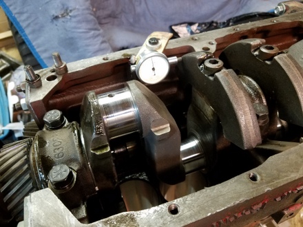
The Jeep was pretty much restored by winter 2018/2019, and the engine served well. Sure, it was a little stinky, and it had various ticking noises, but it was super reliable and consistent......but also with consistent low oil pressure: on the order of 2 or 3 psi at idle when hot. The engine didn't seem to care, but one day I was a little bored so I took off the oil pan and timing cover in order to inspect the timing gear oil jet to see if that was a culprit in my low oil pressure issue.
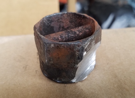
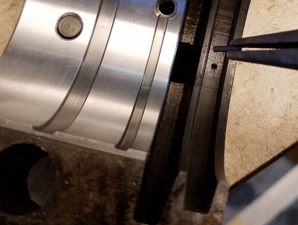
At the start of my quest, I spent a week of head scratching to get the front pulley nut off. I tried 3/4 inch air impact guns. 7 foot bars. It escalated into cutting the nut off....the job went well after that.
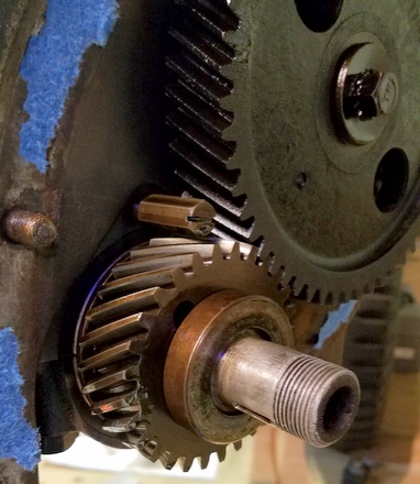
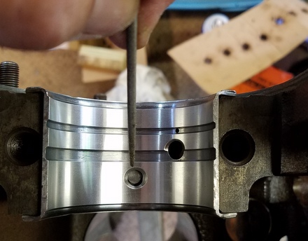
The timing gear oil jet is a small fitting installed onto the end of one of the oil galleries with a hole drilled into it that directs oil onto the timing gears. "Word" at the scuttlebutt is that the jet size on early flathead engines is overly large, at about 0.070" in diameter. In the mid 50's Willly advised that this jet size be reduced to 0.040" which would help increase oil pressure, particularly at the #1 rod bearing. Here it is right in the center of this picture:
This is the large 0.070" hole.
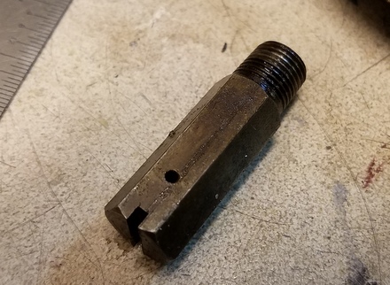
To shrink this "jet" to 0.040 or so, I plugged the hole by drilling it oversize, tapped it with an 8-32 tap, and installed short set screw plug. I staked the plug and then drilled a 0.035" jet hole. The jet was reinstalled, I cleaned up the pan, oil pickup and painted up all the parts so things look a little better under there.
The result of this work yielded about 3 to 4 psi oil pressure at hot idle speed. A rather small gain but it was worth a try.
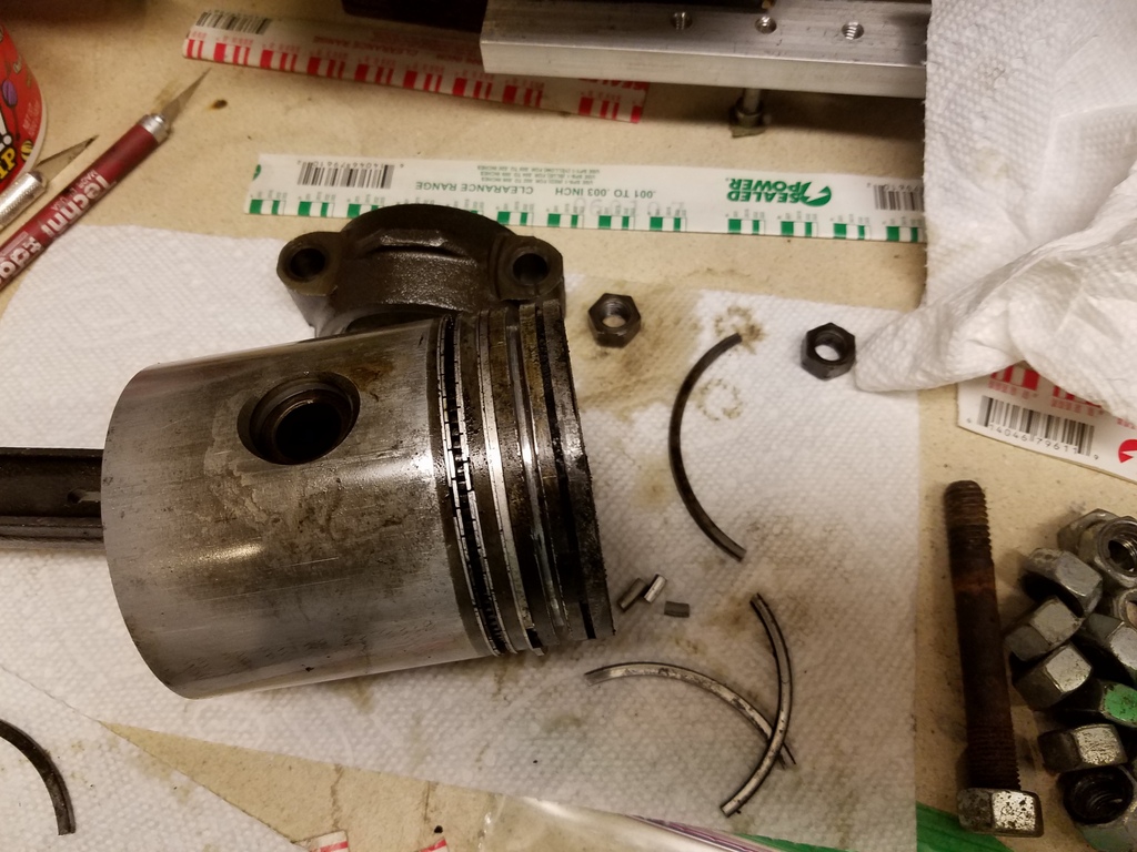
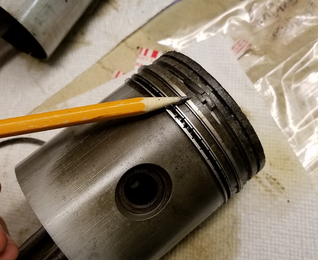
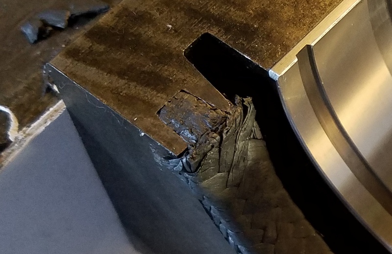
I thought I'd just replace the bearings and maybe the rings too. I pulled the motor, started disassembly, and found that all the top rings in each piston were shattered.
Some were in broken in a dozen pieces or more. I believe that was the source of my light tapping. I planned to replace the rings, but then I found one piston had wedged two pieces of ring, one on top of another, in the top ring land. The ring land was destroyed, so I need new pistons. (Note that the narrow top groove in L134 pistons is not for a ring...it's for combustion gases.)
So the plan was revised to include new standard bore pistons...still not terrible, but...
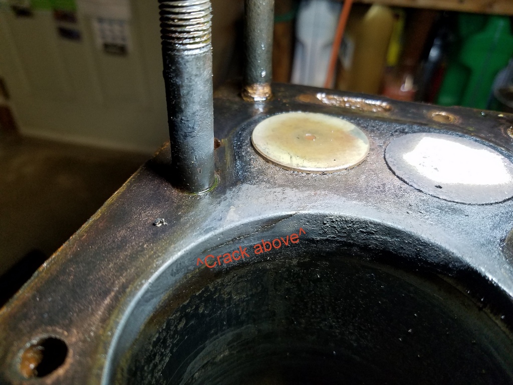
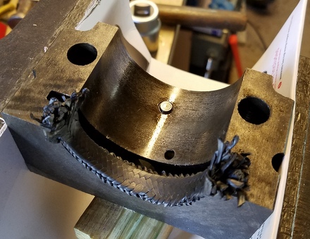
The CRACK
Despite my good clean living, my luck finally ran out. Whilst inspecting the block, I beheld a fine crack in cylinder 4 going from the bore, over the top edge onto the deck. Ugh. On the plus side, it's nice to know why I experienced the occasional mystery coolant fog out the tailpipe. If you click the picture below you can see the crack....
For this situation I would need a professional. The first person I thought of was "MetalShaper" of Youtube fame. I recently realized he was fairly local to me, so I contacted him. He had me bring it to his shop to take a look. He said he could fix it, and he did. He made some videos of the process which I'm linking to below. In the first video, at about a minute in, he starts on fixing cracks in the center of the large coolant passage on the deck, and at about 8 minutes in, he starts fixing the crack you see above...
He has more video of the boring job.
It ultimately required an overbore of 0.040" as there was excessive wear near the tops of some of the cylinders. A honing machine finished the job.
I purchased a set of 0.040" Keith Black pistons, which were easy to find, but it was difficult to find some of the other parts (unless they were exorbitantly priced at some online "marketplaces"). I ended up finding "King" brand main bearings, Crown rod bearings, Crown valves and no-name valve guides. I purchased a Neway valve cutting kit to re-do the seats too.
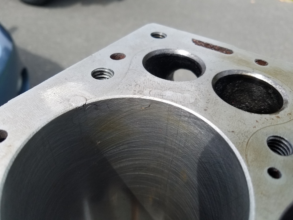
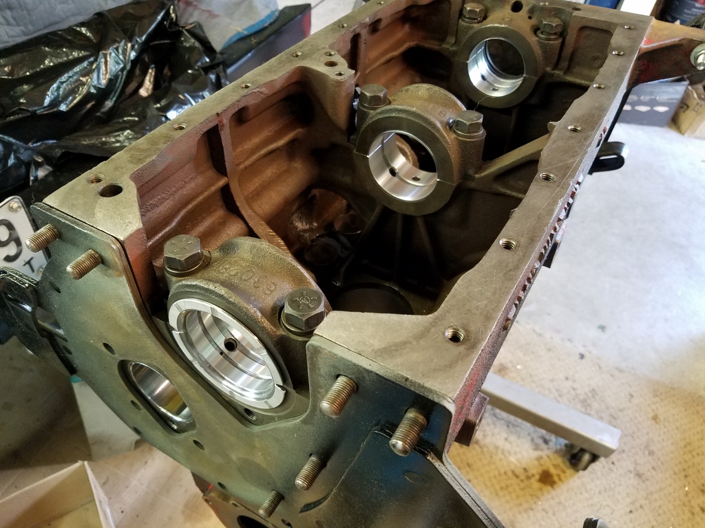
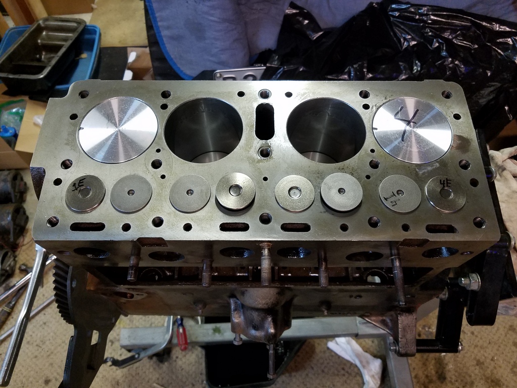
I picked up the engine from Brian in mid-August and it looked great. Here's a shot of the lock and stitch repair on cylinder 4. The top ring does not come up to the location of the pins.
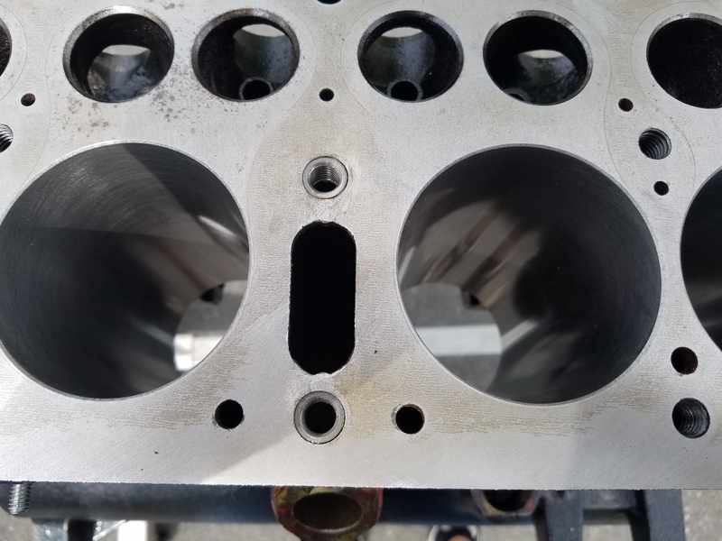
Here you can see lock and stitch pins were also required between the central coolant slot and adjoining stud holes. Threaded inserts were fit to restore the stud holes.
Valve Guides
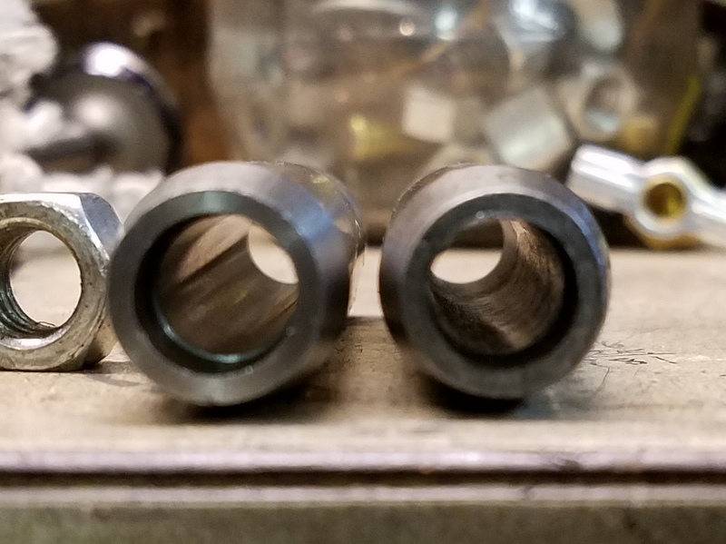
The first task after getting the block back was to remove the old vavle guildes. I used a press for some of them, but ended up using a 3/8-16 x 6 inch grade 8 bolt to pull most of them out. An inspection of the new no-name guides indicated the surface finishes of the I.D.'s didn't look great, so I mounted a more rigorous search for Sealed Power guides. I managed to scrounge some but not a complete set. They were definitely superior, so I used the ones I found along with a couple of the best looking no-names. I used the same bolt to pull the new guides into place. Below, note the bore of the Sealed Power on the left, and the no-name on the right.
After installation, a couple of guides needed a tiny bit of reaming for sufficient valve stem clearance. I think I used a 0.375" reamer.
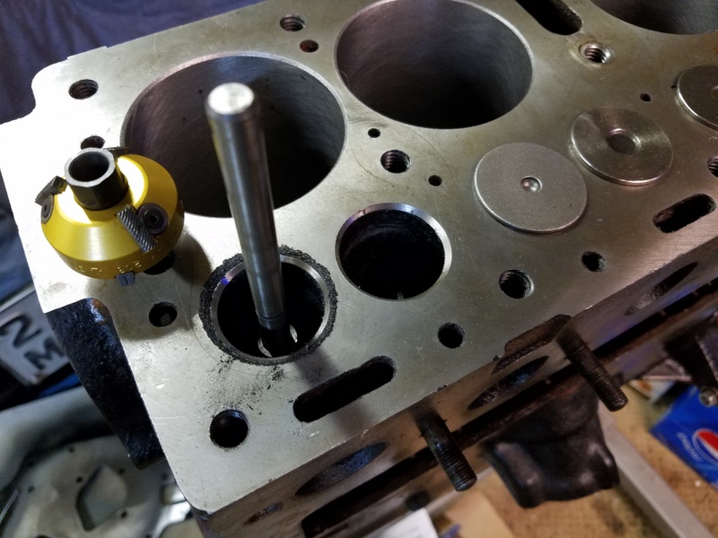
With fresh guides in place, it was time to re-face the valve seats. I purchased Neway P/N CU208 which will cut both 31 and 46 degree angles, and P/N CU205 will do the 60 degrees. These cutters work on pilots that fit into the guides. I got two pilots, P/N PF14038-STD and PF10438-.001 to cover the range of sizes likely for the I.D. of the guides. A handle, P/N TW505 allows you to rotate the cutters. Here's the CU208 sitting next to the seat just cut. The pilot is wedged into the guide.
I cut with the 46 degree until the seat surface was clean, then used the 31 degree to just chamfer the top edge, and then the 60 degree to break the inside inner edge. The 60 degree cutter did not cut very smoothly, but with some finesse, the job came out fine. I fit each valve and checked the contact patch as I went. The Universal Service Manual explains specifications. After the cutting was finished, I did a few spins with the valves installed with some manual valve grinding compound to just dress them a bit and clean them up.
The dirty work was done, so it was time to scrub the block with engine cleaner, then soap and water. I dried it quick and oiled the cylinders.
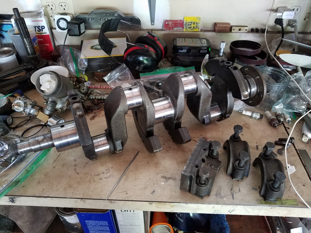
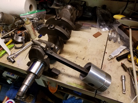
The crank surfaces looked pretty darn good with just a little staining here and there from, I presume, sitting for long stretches. It measured out good.
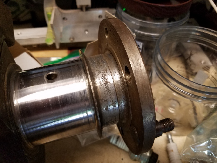
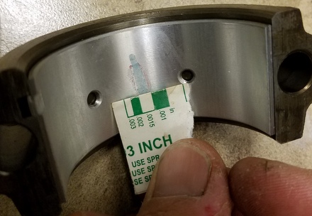
The rear main seal surface was corroded, but I think a rope seal will do nicely here.
I test fit the new bearing shells, and found the front upper did not fit with the dowel. I had to file the hole in the shell oversized to get it to fit. Not a big deal. Here it is before the filing.
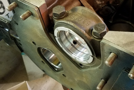
The caps were test fit and torqued down.
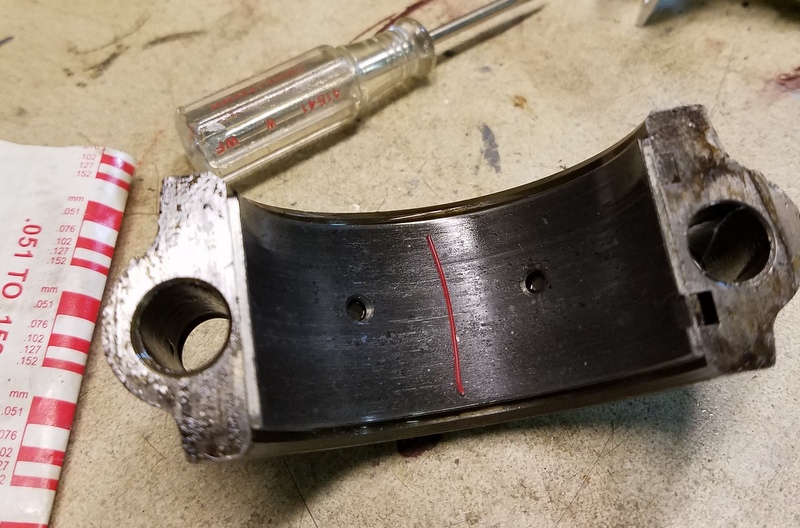
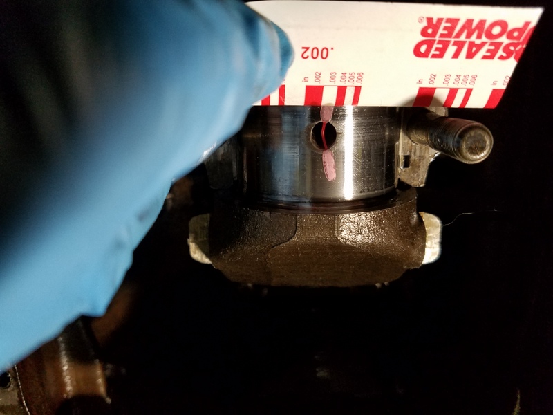
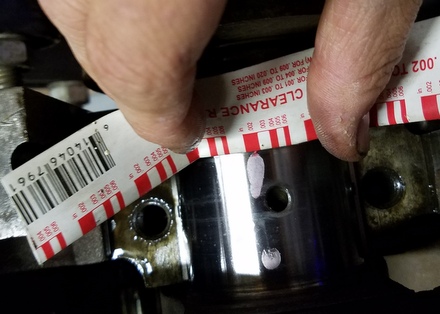
I then installed the crank and checked clearances with plastigage. I was very happy to see the mains came in a bit under 0.002".
The rod bearing clearances were checked at this time also with the crank on the bench. They all came in at about 0.0015".
Cam
Before I got too far installing the crank, I thought it best to install the cam while it was easy to get my hands in there to slip it past the cam bores. First, I had to replace the front cam bearing. Using a home made aluminum puck with a bolt, nut and bar, I pulled out the old bearing, and reinstalled a new one with the same rig. Be sure to line up the oil feed hole with the oil hole in the block! The image below is all I've got of the new bearing.
The front engine plate was installed next, then the cam. I was able to remove and install the cam without ever having to remove the cam gear, so it can be done.
Rear Main Seal
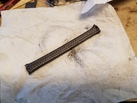
I thought I'd try the fiberglass rope rear main seal that came in my Felpro gasket kit. Right away I had a dubious feeling about it as it seemed hard and unyielding. But I wrestled with it, and forced it into the grooves, used many razors to trim the ends (gad that fiberglass is murder on blades). I then installed the crank, all the while suspecting this wasn't going to work.
And it didn't. With the caps torqued down, the crank wouldn't turn. It was waaaay too tight. After reading all the complaints about this seal on the forums, I decided to just get a "Best Gasket" brand PTFE rope seal kit.
The kit comes with a roll pin, two pieces of rope, a shim, and a cutting blade to trim the ends. You drill a hole in the bottom of the groove of the cap and install the roll pin. It serves to lock the rope in place to keep it from rotating.
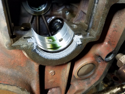
I flattened the rope into a wedge profile to more easliy force each piece into the grooves, carefully mashed them in, and here's what I got:
To trim the frayed excess rope, you place the shim onto the mating surface, and use the cutter to trim off the ends.
After cutting, the rope obviously stands proud of the mating surfaces of the block and cap by the thickness of the shim. This extra height allows the ends to mash into each other when assembled. But, it's important to prevent any strands from folding over onto the mating surfaces, so you should use a tool (I used a small dull screwdriver) to carefully push any loose strands hanging over the mating surfaces up and onto the rope endfaces. Here's the "dressed" rope ends:
The crank was finally installed for the last time and everything torqued down. I checked endplay and it was in spec. I measured about 5 ft/lbs running torque to turn the crank.
Next was installation of the valves, springs and keepers. Lash was set to 0.016".
I measured about 8 to 10 ft/lbs to rotate the crank with the valvetrain installed.
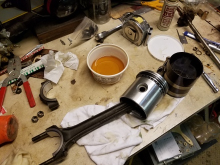
Pistons
The rod/piston/ring assemblies were assembled. The pistons were numbered by Brian (metalshaper) so I of course fit them to the corresponding rods. I fit Sealed Power Kromex rings which have a chromed top ring and chromed oil rings...(the box is old...I don't think these are made anymore). I measured the end gaps of the rings and they were in spec. However, I couldn't leave well enough alone, since I learned that the latest practice in engine building is to gap the second rings a little on the bigger side; this allows the top ring to seal better. Yes, it's absurd to care about this for a Go Devil, but I filed the second rings anyway to achieve 0.017" gaps (from the
as-supplied gap of 0.011"). The top ring gaps are about 0.014". So I'll bet I'll gain a good half a horsepower...haha.
The pistons installed easily and I got the caps torqued down. I did not bother with new "pal nuts" on the rod nuts.
I measure about 10-11 ft/lbs to about 30 ft/lbs to rotate the crank/valvetrain/pistons. The 10-11 ft/lbs is when the pistons are all at the top/bottom of travel (no piston movement) and about 30 ft/lbs when the pistons are in the middle of the cylinders (maximum piston speed as a function of crank rotation). I'm thinking while this seems to be a lot of torque, I think it should loosen up with break in.
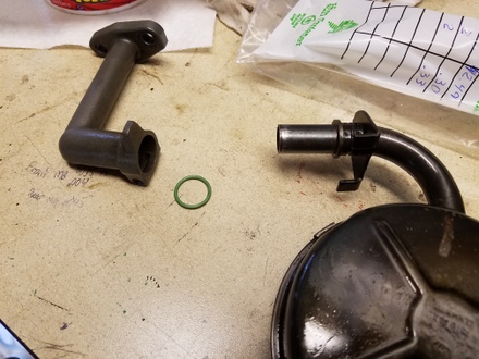
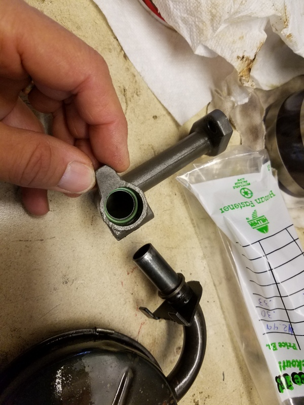
Oil Pickup Mod
I thought I'd try to put an o-ring in the oil pickup joint. There is not supposed to be anything there, but it seems like a decent idea. I could not find a conventional "english" size Buna o-ring size that would fit. In metric sizes, a 14mm x 16mm would be ideal, but I couldn't find anything locally. I then remembered I have some A/C HNBR o-rings laying around in my A/C stuff and it so happens one seems to fit okay. I'm thinking this might just keep some tiny bit of extra sealing when the engine is out of level.....maybe. Eh, I don't think it could hurt.
I installed and bolted down the oil pan, which felt good after all these months of engine parts laying around!
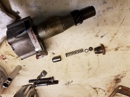
I thought of re-using the original oil pump, so I took it apart to clean it up. The rotors measured to spec, but the bypass system spring was broken and I lost confidence in replacing that spring with an equivalent. Note the broken spring end to the right, and to the right of that is a goofy slotted set screw that someone must have installed in the past to increase bypass pressure...
I bit the bullet and ordered a new (pricey) pump from Rockauto, and was surprised to see it had a date code of 2001 on it. I hoped this unit was from the "good old days" before the faulty batches of pumps hit the market in the late 2000's. It turns pretty stiff, so I worry a little bit...but I bolted it on. Incidentally, the new oil pump has a cast iron housing whereas the original was aluminum.
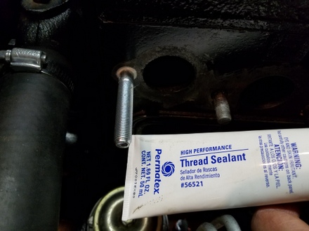
I installed new Dorman head studs and sealed them with Permatex 51813 sealant as recommended by metalshaper.
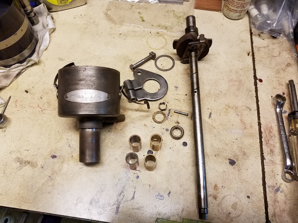
Distributor Rebuild
I took some time to "rebuild" the distributor also. I knocked out the lower retaining ring pin and then installed new bushings (correct sized bushings can still be found at the hardware store). Make sure to add an oil hole to top bushing for oil flow.
The distributor as installed in the block sits on a precision washer (just to the left of the centrifugal weights on the shaft in the picture above) and this sets the height of the distributor body so that the shaft will float between the thrust surfaces between the body and shaft. Mine showed signs of rubbing the top thrust washer, so I made a thinner washer, which set the body down lower in block, and this introduced equal gaps between the shaft features and thrust surfaces.
I installed the distributor into the engine and timed it statically, using a multimeter to check when the points open. I wasn't sure where the distributor body orientation is to be, so I set it so that the oil drip fitting was at the 10 o'clock postion. I may re-do this as I think I'd prefer the oil drip fitting in the 2 o'clock position.
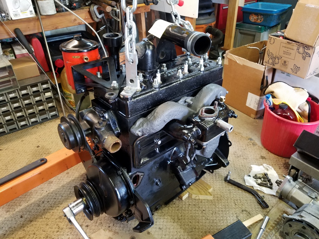
The Remaining Stuff
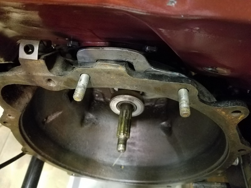
I proceeded to install the head, (which was resurfaced by Metalshaper), waterpump, the oil filler tube, freshly blasted and painted manifolds, thermostat housing, flywheel, new clutch and spark plugs.
To install the engine with a bit more ease, I made up a bracket to tie the top bellhousing bolts together which allows one hand installatoin of the nuts. It makes for a much easier installation of that hardware. Click to see it installed.
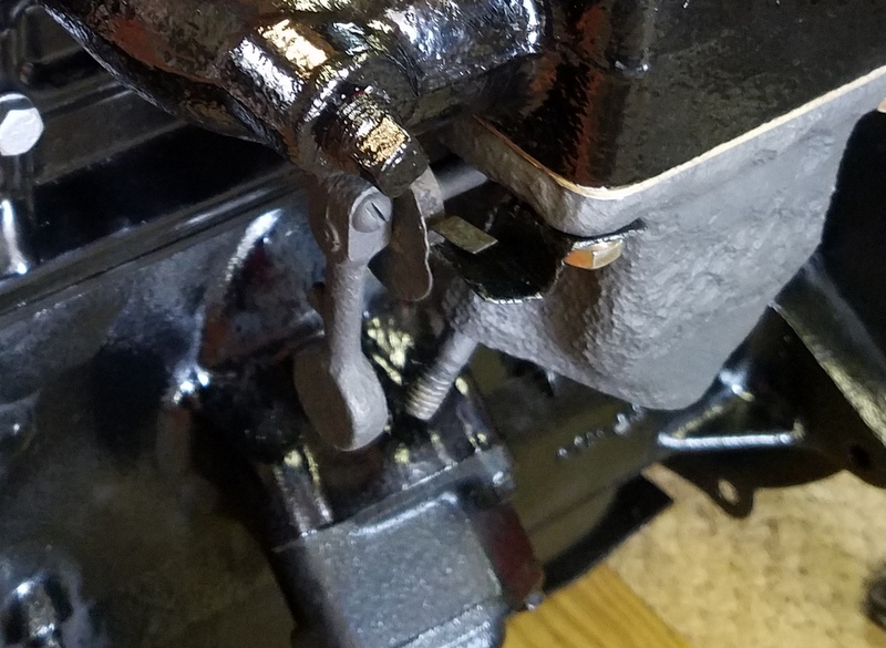
Finally, shockingly, I was able to loosen the exhaust flap counterweight and adjust the bimetallic spring/flap for cold starts. I was even able to reuse the sheet metal tab used as a stop at the end of the spring. It's odd what survives and doesn't in these old Jeeps.
I installed the engine, hooked everything up, pushed it out into the driveway and fired it up. There were a couple glitches: gas leak, coolant leaks, but I sorted it all out. I made a video of the experience:
The manifold stud coolant leak was quite persistent, and after a couple tries I installed a new stud and used Permatex 56521 to seal it up.
I switched to Motorcraft Diesel 10W-30 oil. This has enough zinc and phosphorous for flat tappet engines, and the viscosity is good for this type of engine. I measure about 40 psi oil pressure at idle when cold, and about 18-20 psi at idle speed when hot. When at cruising speed, it's about 45 psi.
The aluminum radiator (an ebay no-name special) is fantastic and keeps temps at 180-185F. I was stuck in traffic (before the rebuild) for a half hour once in 90+ degree weather (at the Simsbury CT Airport Fly-in/Car show 2019) [I just realized my Jeep is in one of the gallery pictures from the Hartford Courant haha! Can you spot it in that link?], and the engine crept up to 200 degrees F, but I used the throttle control to bump up the idle speed to about 1000 rpm, and the temp came down to 190F. I'm happy with that.
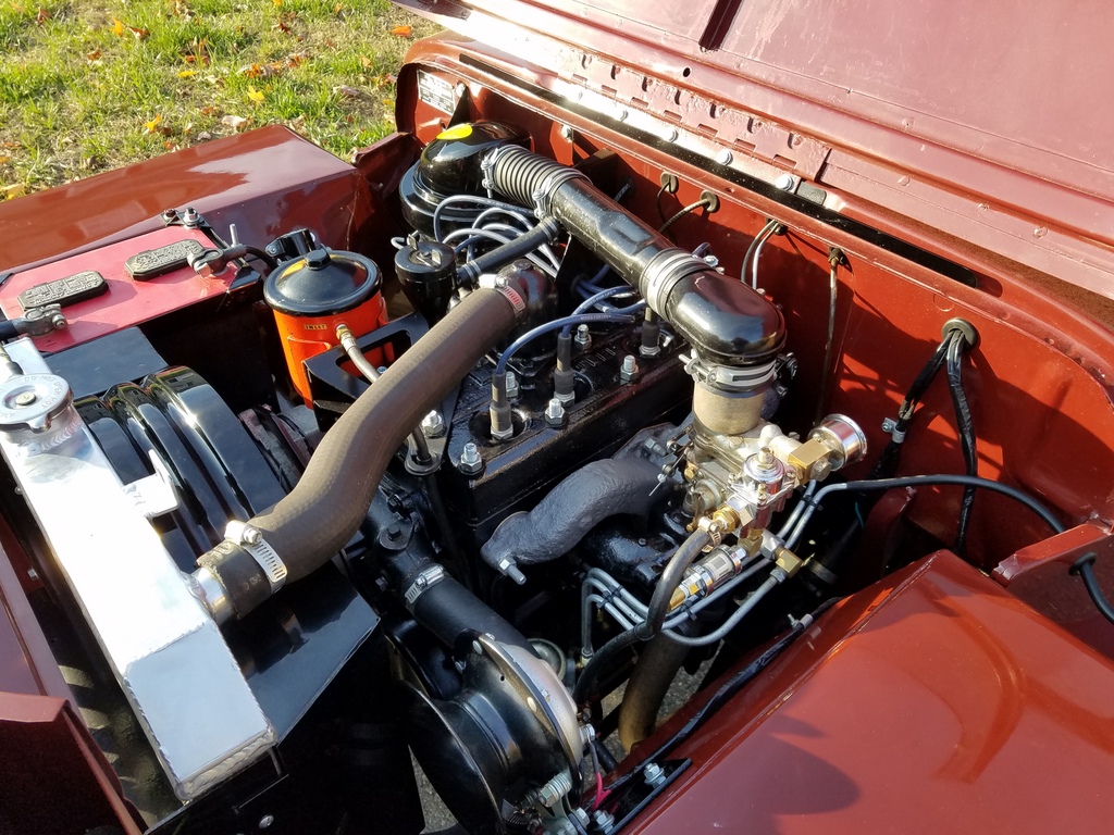
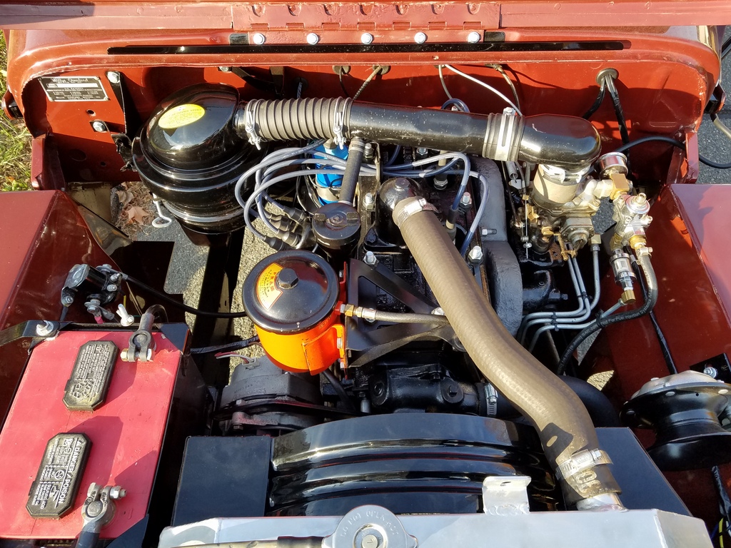
The Finished Compartment
Having the engine out allowed me to touch up paint and some doo-dads, and it looks great. It's definitely not a stock Jeep, but I like the look of the black flathead engine with all the clean details. I drive it every chance I get, whether it's 20 degrees or 90 degrees out, as long as the roads are mostly dry. I have gotten caught in a shower or two, but no deluge yet!
So until the next fun project, Keep on Jeepin'.
To see Willys Jeep CJ3A drivetrain
rebuild, click here!
There exists a nice set of webpages for CJ3A's. It's got a forum too that caters to both '3A's and CJ3B's. It's a great resource, and frequented by very knowledgible folks.
1967 GTO Original Owner
These two videos feature an original owner GTO. This car was featured in Hemmings Muscle Cars magazine a couple years ago. Part 2 has inside and outside shots of the owner driving the car. Very nicely done.
Blues Maker
"Mississippi" Fred McDowell. One of the great Bluesman. This is a documentary made in 1969.
Pinstripes
Pinstriping the ol' fashioned way. Pretty nice.
MGB Racecar
I've always liked MG's. Watch this MGB lift it's inside tire a few inches off the tarmac when going "'round the bend". Awesome.
Pepsi Throwback
Pepsi has put out a "limited edition Throwback" version of
Pepsi with REAL sugar, instead of high fructose corn syrup which has been used since the 80's. Holy cow
there IS a difference; it's WAY better. Find some quick!


 In
2009, I found an ad for a good candidate replacement Go Devil L134 that was pretty local to me. I went
for a visit and found the seller to be a young fellow with a serious
Willys Jeep affliction. He had Jeeps, engines and parts all over the
woods in his backyard.
In
2009, I found an ad for a good candidate replacement Go Devil L134 that was pretty local to me. I went
for a visit and found the seller to be a young fellow with a serious
Willys Jeep affliction. He had Jeeps, engines and parts all over the
woods in his backyard. 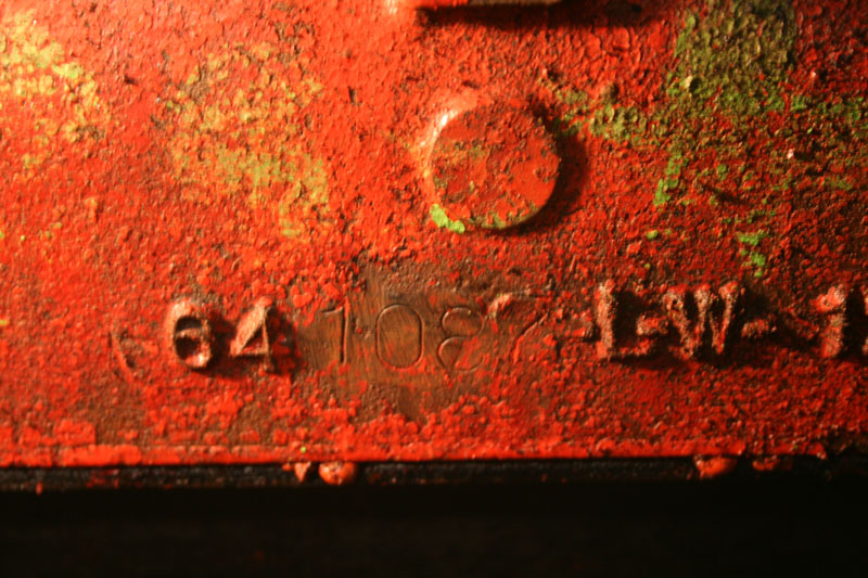 The engine has a casting
number of 641087, but curiously the last 4 digits were ground off and
then stamped with the "1087" And the stamps look old. The engine
was promptly put away in a corner while I worked on other projects, and
years have passed.
The engine has a casting
number of 641087, but curiously the last 4 digits were ground off and
then stamped with the "1087" And the stamps look old. The engine
was promptly put away in a corner while I worked on other projects, and
years have passed.