This page highlights work performed on several systems of my
1967 GTO:
Engine
Quadrajet Carburetor
Exhaust
Rear axle
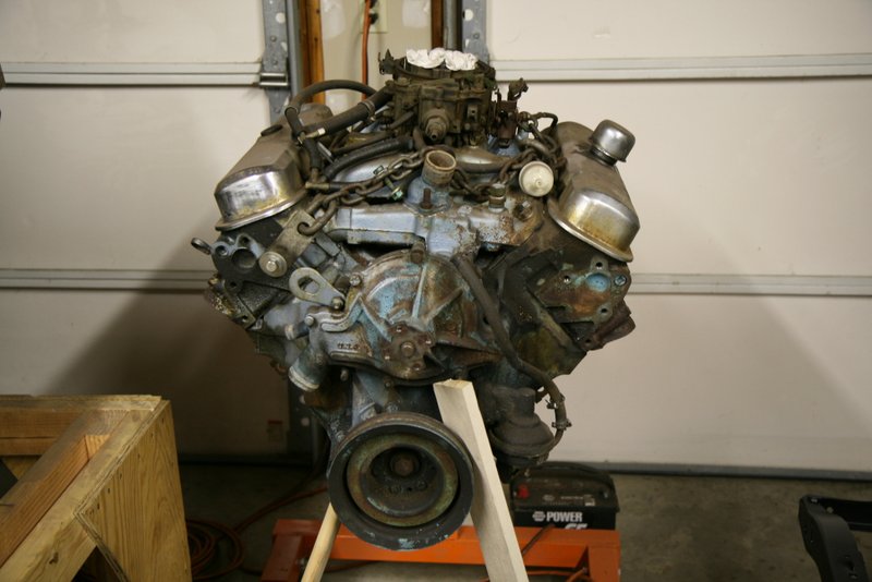
Pontiac 400 YS 335HP Engine
October 24, 2012
During a lull over the winter of 2012/2013, I turned my
attention to the engine of the GTO. I believe the GTO sat dormant for a
while in the
70's before the previous owner purchased it, so during the car's first
refurbishment, he had an overhaul performed on the engine to get it
running good. I did not get any details on what work was performed when
I bought the car, but it did run good for me when I used the car as my
daily driver for a few years.
But, a
couple
decades have
passed since then and it's time to take it apart for a good
inspection.
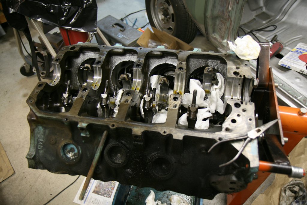
So, during a few evenings I tore the intake, heads and oil pan
off the engine. What I found inside this 133K motor were the original
pistons,
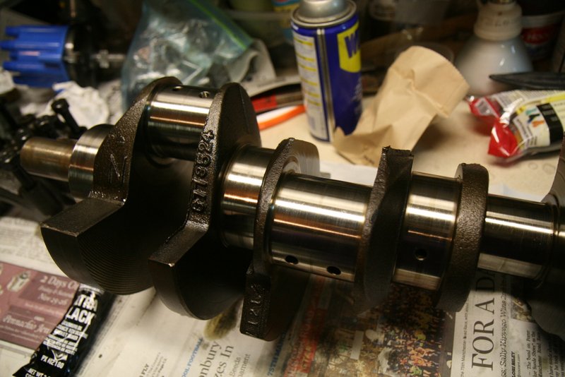
rods, cam and valves. The main caps and rod caps were off next
and
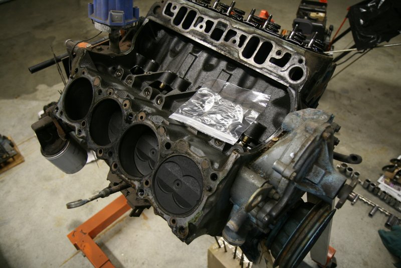
the crank was removed. The crank and all the bearings looked real good,
and the cylinder bores looked really nice with almost imperceptable
ridges.
It looked like the bearings, timing chain
and valve seals had been replaced but there was no evidence of any
machine work. All the measurments are stock spec. It probably had a
ring job with a honing of the bores.
Since the inspection results were good news, nothing will get
replaced but I will clean it up and re-seal everything.
Before putting it back together, I tackled a few broken studs
on the various
engine
parts. I managed to carefully extract a broken exhaust bolt, the
manifold choke stove screw, and a valve cover screw without cutting
into the original threads. This was accomplished with creative
fixturing and the use of a milling machine. It's nice to have end mills
for these jobs.
I took the opportunity to scrape
the tops of the pistons clean, and the heads were also taken apart and
the
valves and combustion chambers were de-carboned and cleaned up also.
Incidentally, I cc'd the 670 heads and found the volumes ranged from 72
to 74 cc's.
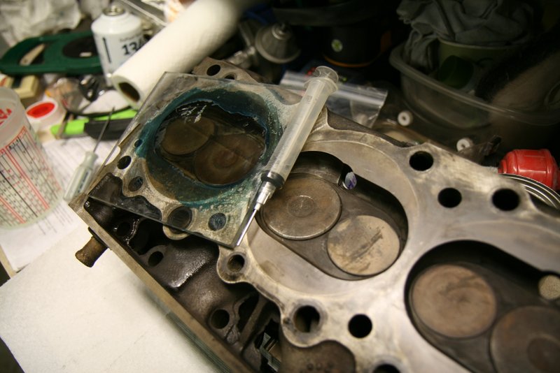
For the rear main seal, I purchased the Best Gasket brand
"Graph-tite" rope seal. The installation is pretty easy with the engine
on an
engine stand.
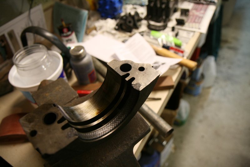
The old bearings were reinstalled into the saddles and
rods, and the crank was reinstalled.
I also installed a pilot bearing into the rear of the
crank. I was happy to find it was machined for a pilot bearing even
though it was born an automatic car. Some automatic spec engines are
allegedly not machined to accept a pilot bearing. Rather than stake the
bearing into the bore, I used Loctite 620 which is a bearing retaining
compound.
The oil pan was very carefully massaged to get the flange nice
and flat, and it was installed onto the block with Utltra Black RTV
and cork gaskets.
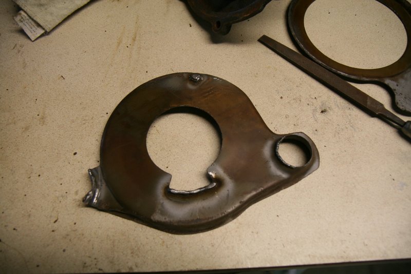
Waterpump gap
The
timing cover required some heli-coil work to repair some stripped out
and corroded bolt holes, but it was salvagable. I also spent a bit of
time on the water pump divider plates. These sat too far into the
cavity which allowed a pretty fair sized gap between the plate and
waterpump impeller. I never had an overheating problem, but it's a well
known issue with Pontiac V8 engines and good practice
to minimize the gap.
In this case, the excess gap was probably due to some
corrosion on the plates where they bear against the backside of the
timing cover cavity, so I welded up the contact points on the plates to
add thickness and filed them down to restore the intended gap. I used a
straight edge to make sure the plates didn't stick out beyond the face
where the waterpump and gasket sit.
Distributor Rebuild
In my experience, points distributors have always been trouble
free, so I'm keeping the points distributor on this car.
I don't
mind at all checking and adjusting the dwell a couple times a year.
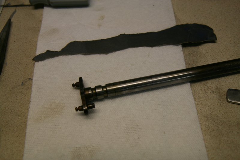
Upon removal, the distributor exhibited sticky rotation, so
disassembly was in order to investigate. With the guts on the bench it
was obvious that the upper bearing (bushing actually) was dirty and
sticky.
The shaft had actually galled up a little bit. There is a grease well
around
the upper bearing, but it
was pretty dry. I cleaned the well out, then used a wire to clean out
the wicking holes that feed
into the bushing, and refilled the well with my own grease
concoction. It is simply some gear oil, assembly lube and lithium
grease.
The distributor shaft required some polishing to smooth the
bushing surface, and after reassembly, it spins beautifully. I
tested the vacuum advance and it
works fine, so it was screwed back on. The Standard
"Blue Streak" cap I bought in the 80's topped it all off.
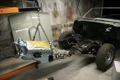
Final assembly
After
cleaning and painting, the engine was united with the
flywheel, clutch and transmission. The heads were left off to ease
installation into the car. Installation was pretty easy with no front
end sheet metal to get in the way.
From there, assembly continued with installation of the heads,
intake, fuel pump, exhaust manifolds and starter. The crank pulley
mounting holes were wallowed out from being loose in the past, so I
welded the damaged holes, ground down the bumpy
welds and CNC'd the six mounting holes so the alignment
would be right on.
I've got an early 70's quadrajet that came with the car, but I
also
have a '79 unit that I might go with and tune it up according to the
Cliff Ruggles book.
This engine is pretty much bone stock,
so I anticipate it might not run very good with available gas.
Depending on how bad it will be, I'll keep a lookout for some different
heads with bigger chambers. We'll see.
First Start
March 2013
Over the course of some weeks I got all the wiring
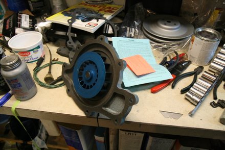
done, and then found the old waterpump leaked like a sieve. Rather than
fuss with trying to find a good rebuilt pump, I bought a new Flowkooler
pump. It's got an interesting impeller.
The only carb I had was an ancient,
choke-less Olds
quadrajet that I've never rebuilt. So that means it's never
been apart for at least 25 years. Yah. (Keep reading farther down
for details of a replacement carb.)
I
managed to put on the wrong year intake gaskets during assembly which
resulted in a
massive hole in the intake exhaust crossover. I also wired
the exhaust crossover butterfly valve closed instead of open.
This made for noisy, cantankerous operation for the first start. And
power was pretty low down! In addition, the vacuum advance
was inadvertently connected to a ported vacuum source rather than
manifold vacuum. Still, I forged ahead with the initial firing.
My son took some video of the first startup, and he posted it
on Youtube. It's not edited much, so avoid viewing the middle few
minutes. We
took it for a spin around the block. It's cold with no windshield. But
it was fun.
After the first run, I fixed all the glitches, gained probably
80 horsepower and the car was
a relative screamer (keeping in mind the car was in strippo
mode
with no glass, seats, carpets, top,
etcetera.) Since then, the car has been loaded up with all it's
accouterments,
and it's back to it's heavy old self. But it runs really
nice and has decent power. It's a time machine in a way, since the
engine has never been rebuilt and is in it's 1967 configuration.
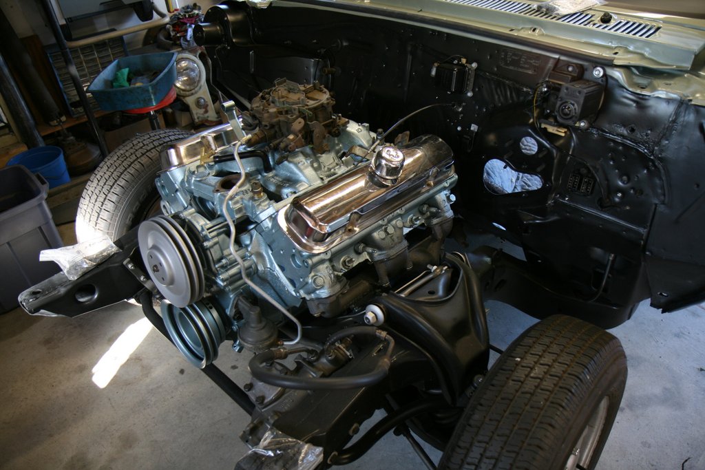
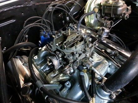
The engine compartment looked pretty good at this point. I still
needed to work on more correct brake booster vacuum hoses, and
vacuum advance lines. Here's the engine configuration
in 2013:
I used the original pitted and scratched valve covers and air
cleaner. I like them because they are original to the car. And
yes, I'm saving
pennies for a correct radiator cap too.
Quadrajet Carburetor Rebuild
January 8th, 2015
Rebuilding a late 70's Quadrajet to a Cliff Ruggles recipe
After running the GTO for a few months, the crusty, clapped out Olds
Quadrajet
that was just not up to my standards. It was cantakerous when
trying to start cold. If it sat for a few days I would routinely have
to pop the hood, take off the air cleaner and partially block the
primaries to choke it a bit to get it to start up. So with the body
restoration done, it was time to get the fuel system to work
like it was meant to.
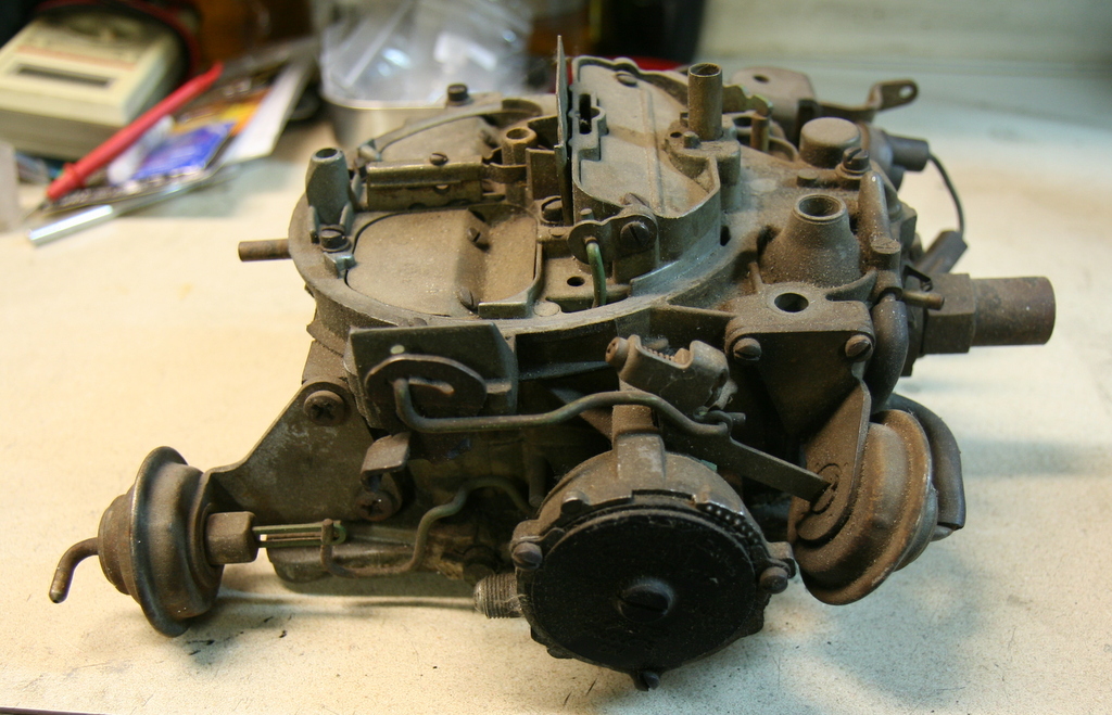
A few years ago I picked up a complete
Quadrajet (with an intact choke system) at a swap meet for 5 dollars. I
had no clue what it was except that it had a front facing fuel inlet
that Pontiacs use. I finally looked up the numbers and found that it is
a 1979 Oldsmobile 403 Quadrajet for a Trans Am. Closer inspection
revealed that, despite the dirt, it was in excellent
condition.
I
picked up a Quadrajet book written by Cliff Ruggles: How to
Rebuild and Modify Rochester Quadrajet Carburetors. According to
Ruggles, these late model QJ's
are good "core" carbs to work with for almost any application. As I
found out, it would need modification to optimize it's
performance for a car from the previous decade.
In addition to
the book, I purchased a complete rebuild kit from the Cliff Ruggles
website for a stock rebuild. The Ruggles kit is quite comprehensive,
and had everything needed to do a complete rebuild.
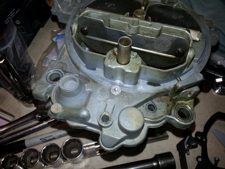
Carb teardown was straight forward and all parts were
organized and cleaned with
lacquer thinner. These late 70's carbs have hardened caps over the idle
mixture screws in the throttle plate to prevent "tampering". The
throttle plate has to be slit with a saw so that a punch can catch an
edge and knock the plug out. The hacking results in an ugly throttle
plate, but it's necessary in order to have adjustable idle mixture
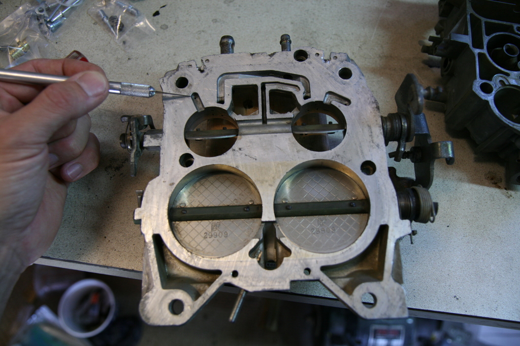
screws. In retrospect I should have cleaned up the hack marks and made
it pretty, but I can pretty it up at another time. In the photo below,
you can see the crude slits at the edges above the small primary bores
on the
throttle plate:
Initial Tests
To
get a baseline, I rebuilt the carb to stock '79 specs with the
intention of performing mods/upgrades one at a time.
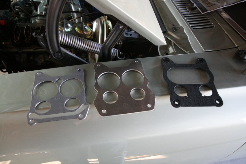
To bolt this "late' carb to the unique '67 only intake, I
fabricated an aluminum plate to block off the front heat passage. (No,
I didn't want
to tap those passages for pipe plugs.)
So the custom plate is sandwiched between a stock '67 gasket and a
later model
gasket on top that matches the '79 Olds carb.
My first road tests with the '79 spec carb yielded a surging
idle, and pretty weak acceleration performance. Attempts
at adjusting the idle mixture screws had no effect on the surging idle.
According to the Ruggles book, if idle mixture screw adjustment yields
no change, this indicates that the idle mixture circuit is too
small.
To fix this problem, the carb had to come completely
apart. It became obvious the carb was pretty far off from optimum tune,
so I decided to just
perform all the mods called out in Ruggles book for a "stock
performance" rebuild.
So here's what I did:
Enlarge Idle Mixture Circuit
As
mentioned above, the late Quadrajet idle mixture circuits are likely
undersized, so I basically used the settings called out in the middle
column on page 94:
Idle Tube ID: left stock at 0.035" (recipe calls for 0.036")
Idle Down Channel enlarged from 0.041" to 0.046"
Upper Air Bleed left stock (0.069")
Lower Air Bleed left stock (about 0.070")
Holes behind Mixture Screws enlarged from
about 0.074" to 0.089"
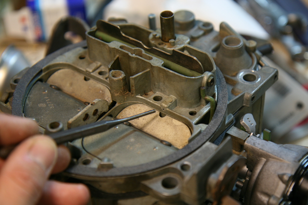
Bypass Air Holes
This
"late" Quadrajet had no bypass air holes, probably because these later
carbs get their bypass air from their hot air choke housing...since
this application will not
use a hot air choke, I plugged the vacuum/air hole in the choke
housing and drilled 0.055" dia holes into the throttle plate
as shown in the picture above (I'm pointing
to one of the holes with the x-acto knife).
Main Jets
I
did not change out the stock #73 jets or #55P rods. The jet/rods size
ratio is a bit skewed from the optimum ratio recommendation but I'm
sticking with them for now. I also left the power piston screw in its
stock location at this time.
Road Test #2
The
carb was reinstalled and the idle mixture screws now had an impact on
tuning. There was a vast improvement on idle quality and low speed
cruise. Full throttle blasts still seemed rather sluggish however, so I
took the carb off for work on the secondary system.
Secondary System
I ordered Edelbrock "CE" secondary rods and installed
them.
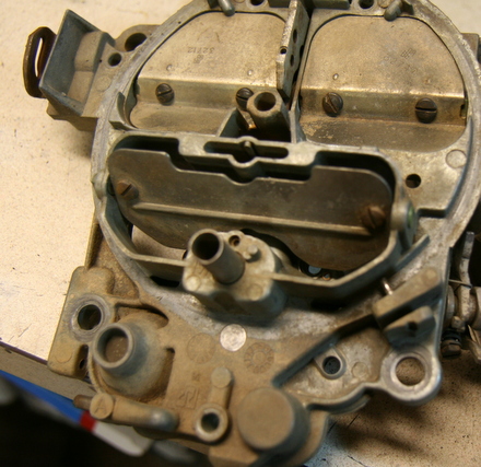
I
drilled out the secondary discharge holes from stock 0.029" to about
0.033". Don't be fooled like I was initially; these discharge
holes have a large ID visible, but deeper in these
holes the
ID is smaller, and this is what you want to modify...the holes are in
the main body casting of the carb; I'm pointing to these holes in the
photo below.
In
addition,
I also added small cutouts (see Ruggle's book page 106) to the
air
flaps. This helps atomize the fuel when it is initially
discharged from the secondary circuit and the flaps arent' quite opened
up yet.
I also did a minor adjustment to the air valve spring for
quicker opening.
Road Test #3
The
performance was better, but I still had some suspicions about the
primary side of things.
Tip in Test....Lean or Rich
I
did the fast idle "tip in" test described on Ruggles book page 99. This
test indicates whether you are running on the lean or rich side for the
primary circuit. Basically, you set the idle speed screw on the
throttle linkage to run the engine about 2200 rpm (engine warmed up)
then choke the engine a bit either with the choke flap or your hand
over the primaries. An RPM increase of about 100 RPM indicates a
borderline lean condition that is considered good. If the RPM's
increase much more than 100 RPMs, your engine is running too lean. If
the RPMs don't change or go down, pull a vac hose somewhere to
introduce more air and see if the RPM's go up. If so, this
indicates a rich condition.
In my case, when I choked it a
little bit, RPM's went up about 250 RPM, so I was running a bit lean.
I'm not quite ready to swap jets or rods, so I decided to adjust the
power piston that (on these late 70's Quadrajets) offers some range of
adjustment for tuning fuel flow.
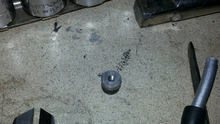
Power Piston
The power
piston screw can only be reached when the carb air horn is removed.
This is obviously labor intensive when tuning. But a small aluminum
plug/cap can be modified to allow power piston adjustments without
taking the carburetor air horn off. You can see the plug at the lower
part of the air cleaner mounting surface, just forward of the float
bowl vent:
With
the airhorn off, simply tap the plug out and modify it with a blind,
tapped hole. I went with a 4-40 thread. Now, with the carb back
together, the plug can be removed by simply inserting a 4-40
screw
and using it as a puller to pop the plug out and do adjustments.
I
turned the power piston out 1.25 turns CCW to richen up the part
throttle operation. Embarassingly enough, I still haven't re-tested it
with the tip in test. I did do more road testing however:
Final Test Comments
More road testing indicated that short
acceleration
blasts don't last long enough for the secondaries to really kick in.
The slow-to-respond secondaries problem seems exacerbated by having a 4
speed with the associated vacuum spikes whilst shifting...(I
don't speed
shift...it's a cream puff for cripes sakes.) The stock 1979 vintage
choke pull off diaphram bleed
rate is just too slow for a speedy kick in of the secondary system.
[The
old carburetor I used had NO choke pull off, and surprisingly, I never
had a bog problem. I don't know what that really means as far as
how good the tune was in that situation, but I sure did like the almost
instant engaging of the 4 "barrels".]
So, I still think
there is more power lurking in my tuning. My intention is
to modify the choke pull off for faster action. I purchased a
new
"Standard" brand choke pull off for 10 bucks (Amazon!) and soon I will
modify the bleed rate on it and try it out. Ruggles book describes
methods for doing this. I'll post the results when I get to it.
Choke
The
orginal '67 carbs used a "divorced" choke which basically means the
temperature sensative element (bimetallic spring) is mounted directly
to the intake manifold exhaust crossover for direct heating. A rod
connects the spring to the linkage on the carb. Later carbs, like the
Trans Am carb I have now, use a choke housing mounted to the side of
the carb, with the bimetallic spring inside. These later housings get
their heat by having a small vacuum "leak" inside the housing which
pulls air through a tube inside the intake manifold exhaust crossover.
The air gets heated up on its trip through the tube.
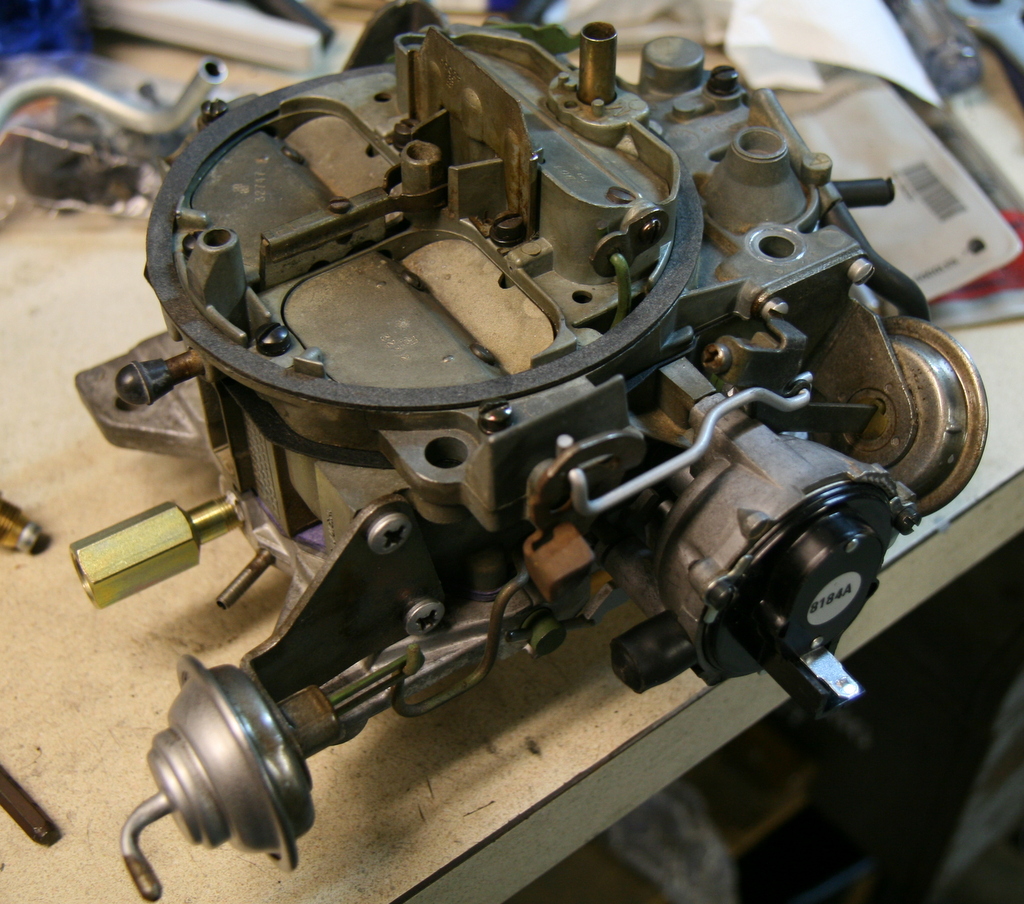
There
isn't an easy way to adapt this late style choke housing requiring hot
air to an early divorced choke manifold car which uses direct heating.
A 20 dollar
solution is to convert to an electric choke. These are available all
over the place, and I got one from eBay. Here it is installed into the
choke housing:
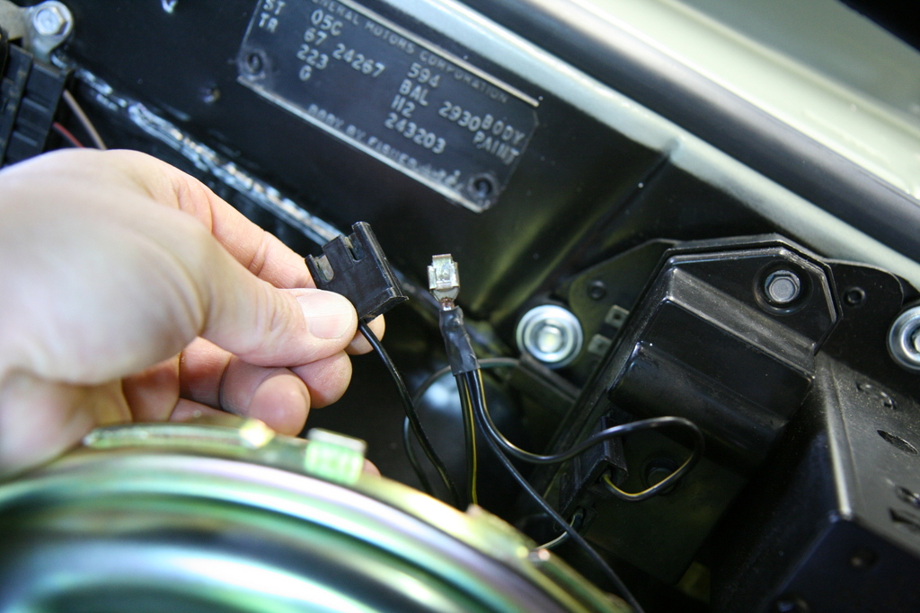
The
electric choke requires a constant 12V source which is not supplied on
an old fashioned GTO engine harness, so, a popular solution to this
problem is to tap into the nearby wiper motor harness.
I
popped out the existing power lead from the connector, and tapped off
of it by soldering on a new pigtail, added some heat shrink, put the
lead back
into the connector and reinstalled it into the wiper motor terminals.
The other end of the pigtail was terminated with a simple female spade
and installed onto the new electric choke. Purists
will immediately notice the non-stock choke, but for me, it beats
trying to find a 60's divorced choke Pontiac Quadrajet.
Techniques
for adjusting the choke linkage is a simple matter of inspecting all
the parts,
installing them, and then tuning them to specification. The subtleties
of how a choke works is something I never really paid attention to
until now. The most important thing I think is to have the choke pull
off adjusted correctly, so that it pulls the choke open by the
specified amount (about a 1/4 inch in my case) immediately upon
starting. It's equally important to have the choke flap completely
closed during the cold start for maximum choking.
After
careful setup and adjustments, it WORKS. It works fantastic!
In
all my days of driving 60's cars, I never really had a good working
choke.
It's amazing that I can leave the car sitting for a few
weeks, get in, pump the carb once to "set" the choke and it fires right
up. In fact, over this winter, after sitting undisturbed for 3 months,
I got in the car, pumped the pedal twice and it started right up and
fast idled. Shocking. The GM engineers knew what they were doing!
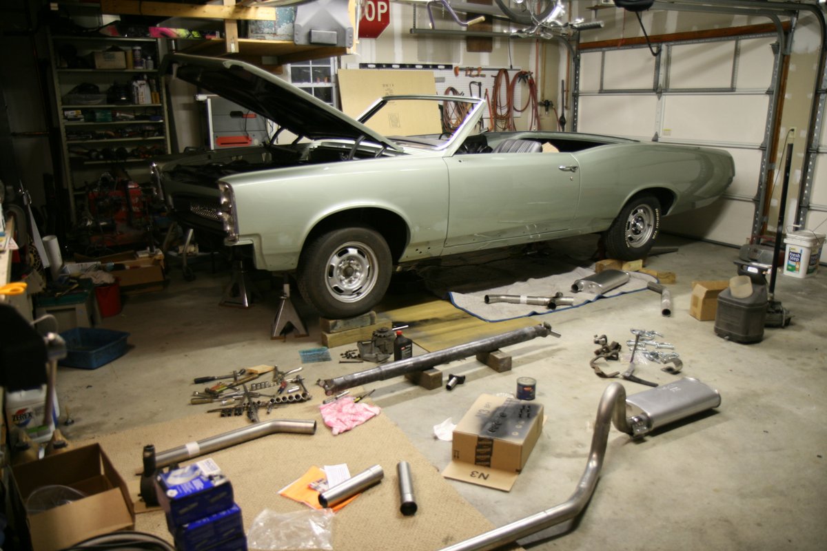
1967 GTO Exhaust Installation
January 31, 2013
These are dark days for car work in the cold northeast, but
with my little 5kW heater buzzing away, I managed to
install a new exhaust system onto the GTO in tolerable comfort.
There are a bunch of options for dual exhaust systems for
GTO's nowadays. I would have preferred a totally stock type system, but
those are too much money, so I decided to go with a Pypes X system with
a pair of Dynomax 17749 long case
mufflers. I think this combo will give me a pretty quiet system which
will be fitting with my stock restoration.
While the price for the Pypes A-body pipes wasn't too spendy,
an
additional
"cost" that some folks may want to consider is the labor required to
tweak this universal-type system for a better fit. I have the tools and
time to put into it, so with some trimming, cutting and welding, I got
the system to fit pretty decently.
Downpipes
I started with the downpipes (headpipes). I am using plain old
"log"
manifolds, and Pypes does make downpipes to fit these.
These downpipes were the best part of the whole system. They fit
perfectly and required no work. There was no indication which pipe was
for which side, but it was clear in my situation that they fit best
only
one way. When bolted on, there was plenty of room around the
starter, control arms and oil filter, and they don't hang
down too low.
The
downpipes must be
cut to length depending on where you want the "X". The "X" is made
assuming the downpipes are parallel to the centerline of the car, but
in my case the driver side pipe angled toward the centerline by about
10 degrees. So, I made my first modification to the short 45 degree
elbow that
adapts to the "X" section. The 45 degree elbow on the
driver
side was notched and then welded
to change the angle to about 55 degrees. The photo below shows the
slice and weld job on the elbow closest to the bottom.
Welding was very easy with just plain ol' steel wire on my
MIG. It works
great on the stainless. The resulting mystery alloy of weldment will
eventually rust, but I'm sure it will last for a very very
long time.
I
used Walker stainless band clamps to clamp the "X" on. They
worked pretty well despite the huge bolts being in the way on some of
the joints.
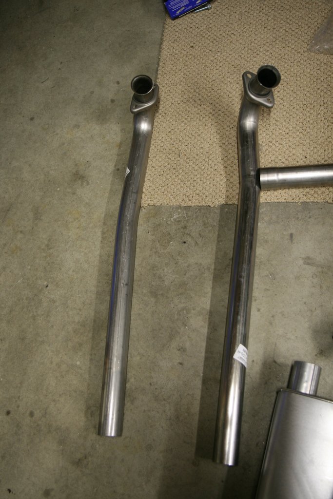
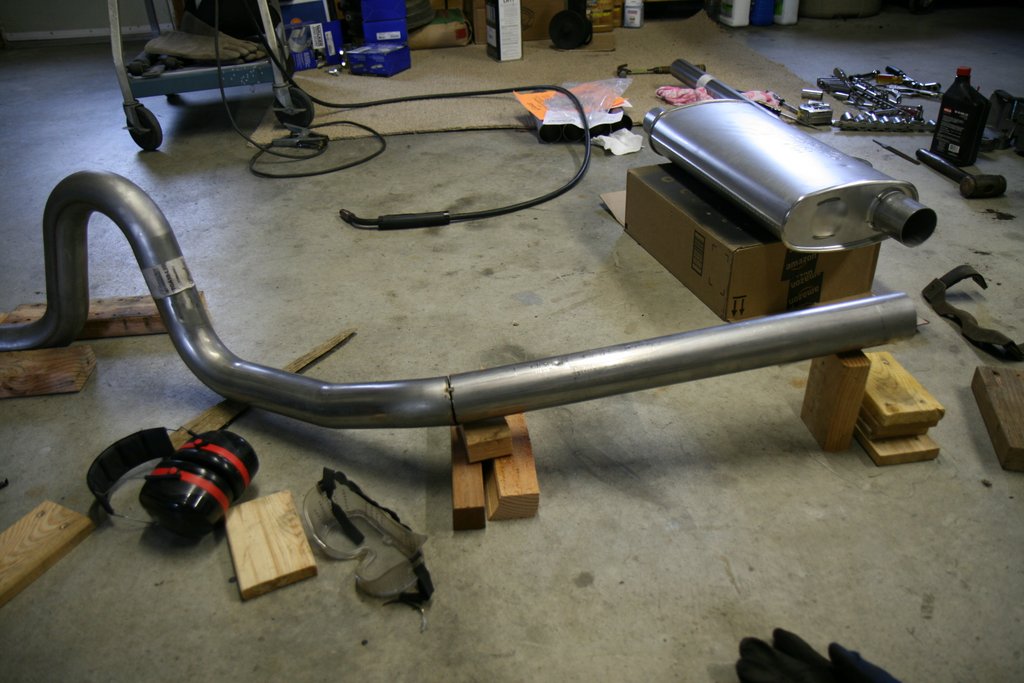
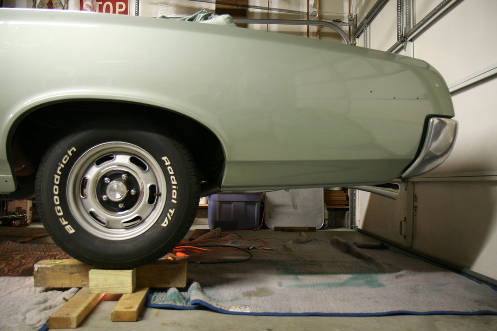
Tailpipes
With
the "X" in place, and before
tackling the intermediate pipes, I began working on the tailpipes and
mufflers. The car was boosted up on blocks (under the
wheels) and there was enough room for the tailpipes to be slipped
over the axle with the suspension at ride height. This made
the constant fitting and re-checking pretty easy.
Trial fitting the tailpipes showed that the tailpipe inlet
ends in front of the axle hung too low (for my taste anyway).
If I attempted to move the tailpipes higher, the tops of the
loops over the axle
hit the trunk pan.
To
compensate, a little over an inch was cut out of the front part of the
tailpipe
to effectively raise the inlet up 1 inch. The new inlet location raised
the
mufflers up nicely and closer to where a stock system
would have them.
With
the front part of the tailpipe modified, a second problem revealed
itself
which is typical of these Pypes systems: The rear part of the tailpipes
are straight, and the pipes make a straight shot out the back to exit
under the bumper. This makes the tailpipes plainly visible from the
side of the car, which I really dislike. So some more mods were
necessary.
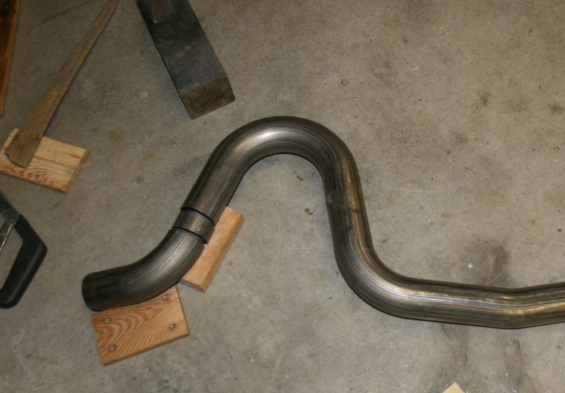
To
address the drooping tailpipes, I sliced a wedge out of the tailpipes
at the
forward part of the straight section (just after it passes under the
frame) and bent the pipes exits up 3 inches. In the photo below, the
tailpipe has already been sliced and the exit end moved up. Before
modification, the exit end was even with the stack of 1x3 wood scraps
to the right.
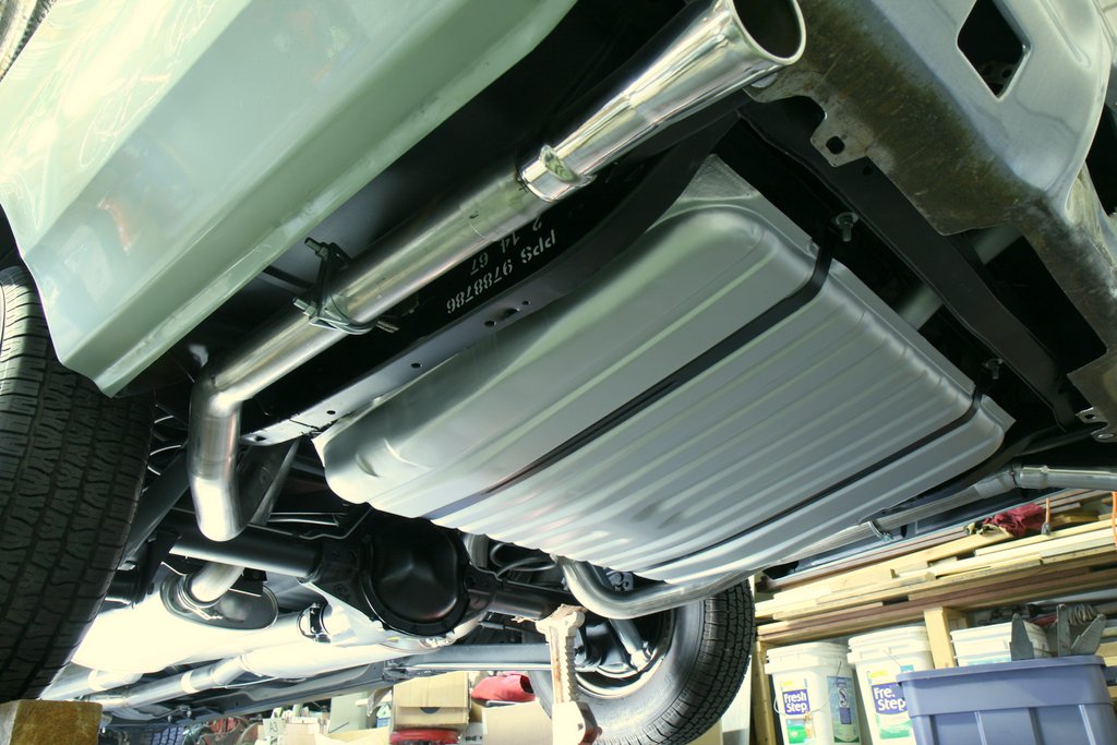
This
mod tucked the tailpipe up in between the frame and the rear
quarter so it was now hidden from view from the side. You can see the
gas tank peeking out under there, as well as a "U" clamp for the hanger.
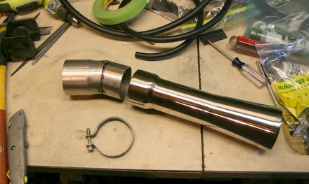
To get the exhaust exit pointed down and away from the bumper,
and since I am using exhaust extensions (stock style
trumpet tips), I
fabricated downturns for the ends of the
tailpipes.
These downturns were fabricated with a simple angle cut and
weld modification on some extra straight pieces included in the Pypes
kit. Fortunately these extra pieces feature swaged ends to fit over the
end
of the tailpipes.
I'll put a slice into the trumpet and use some homemade band
clamps to hold them onto the downturns.
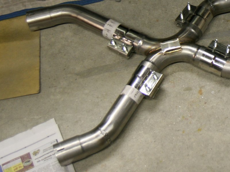
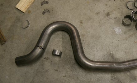
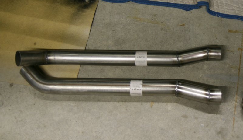
Intermediate Pipes
Finally
I worked on the intermediate pipes that connect the "X" to the muffler
inlets. These sections are supplied as straight pipes with very short
45 degree elbows at the forward ends to connect to the "X".
These
intermediate pipes have to hang low a bit to get by the lowest part of
the floorpans and the exits failed to meet up very close with the
mufflers. So I fabricated
"jogs" into the intermediate pipes that moved the pipe outlets up
higher and
a
little outboard to meet the muffler inlets.
Below is a picture of the "jogs" I put into the outlet ends.
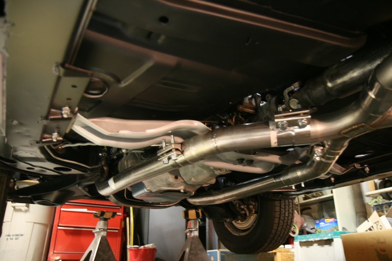
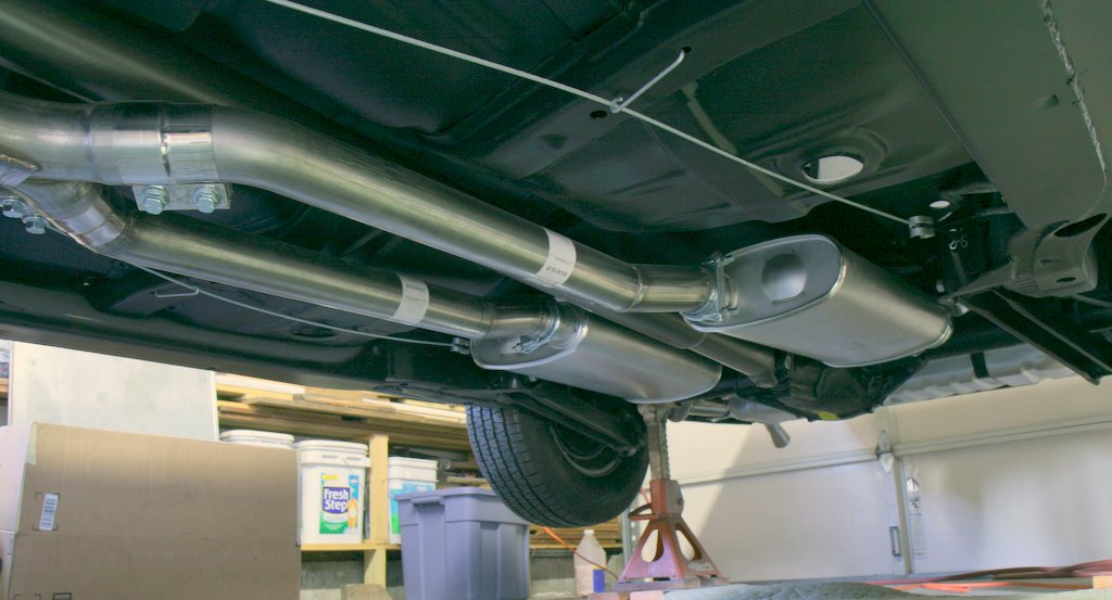
Here they are installed. The "jogs" let the mufflers sit up
higher and keep them a comfortable distance from the driveshaft.
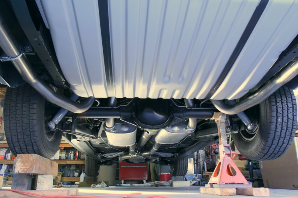
Detailing the Undercarriage
While
the car was boosted up in the air, I took the opportunity to install
the emergency brake cables (new manual trans lengh cables), a manual
trans driveshaft, gas tank, rubber lines and gauge wiring.
I also
re-created the inspection dabs of paint that I found during
disassembly. These included a big yellow dot under the differential
housing, red and orange marks on the spindles, and markings on the rear
frame rail.
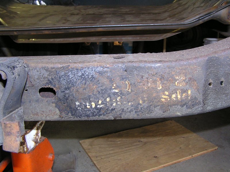
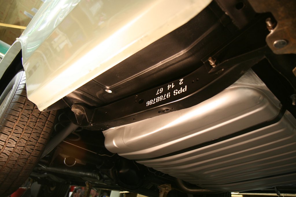
To recreate the frame markings, I made a stencil from a sheet
of paper and cut out the
text, and used a mini roller with white paint.
Here's the stencil I found under the undercoating in 2005:
It's
an upside down stencil with "PPS" for Parish Pressed Steel, "9788786"
which is the part number (for an automatic convertible frame),
and
the
date which was "2 14 67". Since I'm not undercoating, I'm
letting it all hang out:
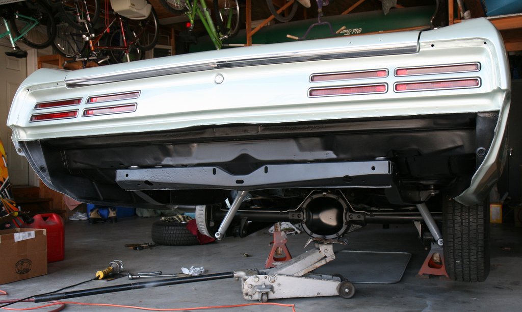
And here's the final glamour shot: (I fitted the old bumper at
this time to fit the exhaust)
I'm going to get rid of the big "U" clamps on the hangers also
and use some more homemade band clamps.
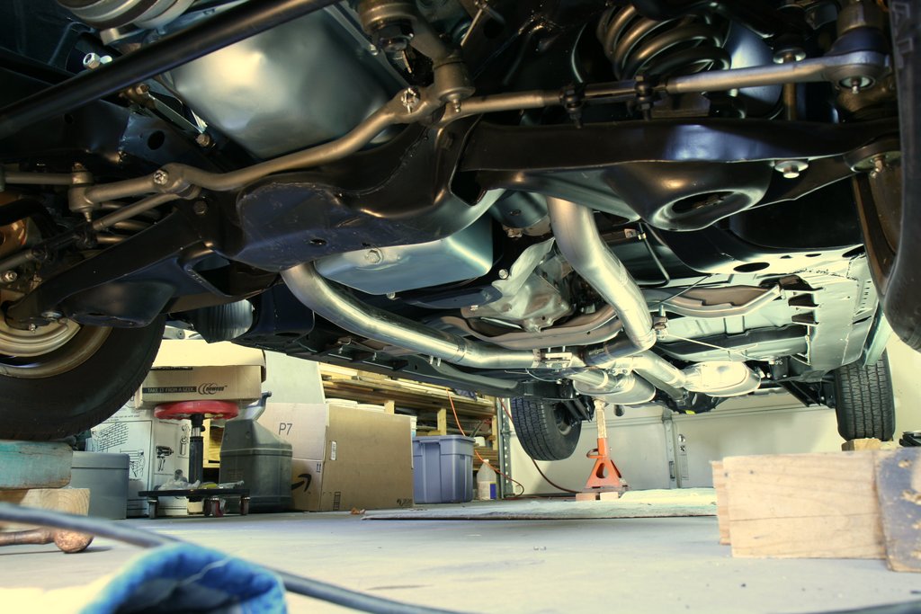
Here's a couple shots of the completed undersides:
EDIT: I ended up removing the driver side pipe and muffler
again to
move that side up a bit more....to make it even with the passenger
muffler. Much better...perhaps a picture soon...
Rear Axle Refurb on the GTO
December 30, 2012
Even though it's been decades since I've driven this
car, I do remember the rear end making a racket. So when I
was doing the frame refurbishment a while back, I removed the axle
cover and looked around in there. I noticed
the differential case had side to side movement within the axle
housing. I should have fixed it then, but I didn't have the gumption.
So one day this week I jacked up the car and removed the axle assembly
so I could see what could be done.
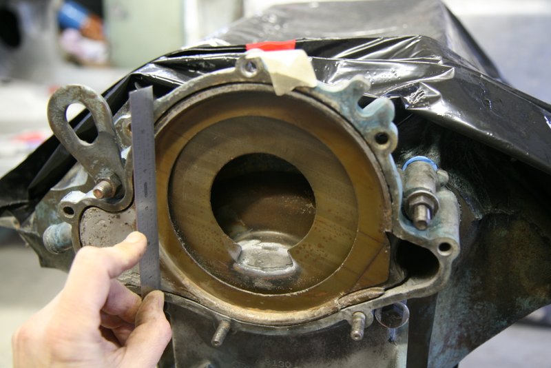
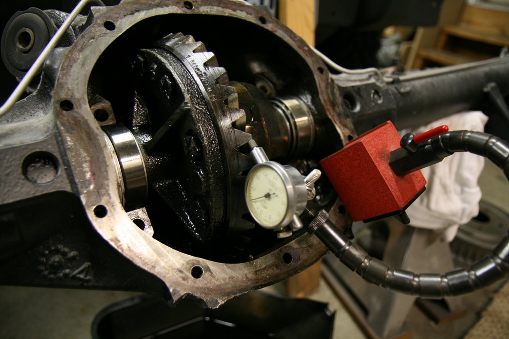
The
differential case has tapered bearings pressed onto each
end, and the outer cups are clamped into the housing with caps and
bolts. An intentional bearing pre-load should be present by having an
interference fit of the case into the axle housing so there should be
no side to side
movement. However, I measured a side to side movement of 0.020", and
the ring
gear backlash was 0.023". Both numbers were not good and
something was bad here.
After removing the axles, the differential bearing caps were
removed. I was careful to
keep the
caps marked so they could go back into the same side, position and
orientation. If the caps are mixed up, the matching
machine tolerances will be disturbed and
potentially destroy
the rear. The case typically must be lightly pried out, but in
this situation it just lifted right out.
Under
the caps and between the races and housing are custom
machined spacers from the factory that set the side to side
position of the diff case in relation to the pinion gear. As built by
GM, these spacers are cast iron, and they are intentionally a few
thousands too thick on each side. This introduces pre-load onto the
differential case bearings. When taking the rear apart, take care not
to mix these spacers up as they will be a good reference when
reinstalling the case.
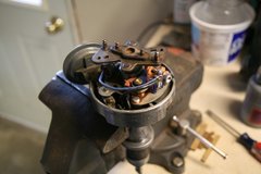
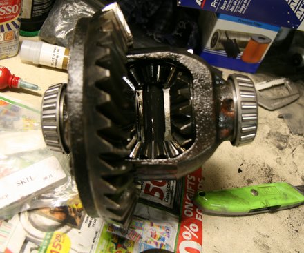
Upon
removal of
the case, it was evident that the bearings had worn down significantly.
The rollers for both bearings looked fine, but the outer races
were severely galled and had some deep pitted areas.
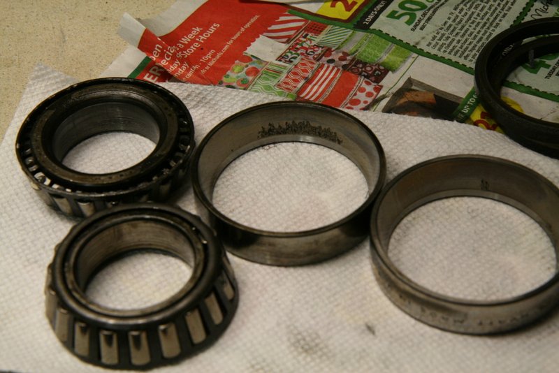
I pulled the bearings off of the diff case
and it appeared that one of the bearings also spun on the diff case
which slightly galled the surface.
Despite
the damage, it looked like it was repairable. The pinion looked good
and spun nice with a bit of drag like it should. The ring gear looked
good, and the spider gears looked okay.
A search was undertaken
to find bearings and seals. I learned that finding these kind of parts
locally on a shelf is not very likely. I did find the diff bearings at
a NAPA, but I could not find axle seals, or axle bearings. I ended up
buying parts from Amazon of all places.
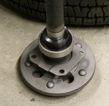
I
installed the new bearings onto the differential case with a hammer and
bearing driver. (I don't have a hydraulic press. Yet.) Bearing
retaining compound was used as an extra measure.
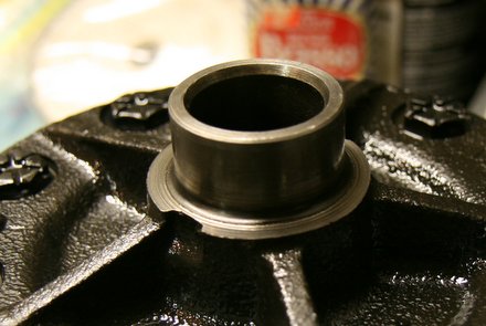
For
installation of the diff case into the axle housing, PMD service
procedures recommend new steel shims instead of re-using the original
cast iron units. Since I kept the originals for reference, it was a
simple matter to stack some steel shims to match the originals. A cast
iron spacer is shown next to the new shims.
Initially,
you subtract a few thousandths on each shim stack so the case can go in
and out with no interference, but you don't want free-play either.
Initial measurements can be made more easily this way.
I
measured 0.007" backlash on the ring and pinion on the first try with
the new shims set to original specs. I then added 0.005" to the shim
stack on the passenger side which introduced the required pre-load.
Putting the extra shim thickness on the passenger side also pushed the
ring gear a bit further away from the pinion, and a
re-measure of the ring and pinion backlash indicated 0.009"
which
is probably a better number for used gears. I did not go to the length
of getting compound and checking the gear contact. I figured since the
new shim stacks ended up being within a couple thousands of
the
original shims, I should be okay.
After torquing on the caps,
the axles were installed along with a new wheel bearing and seal on one
side. (I did the other side a couple decades ago)
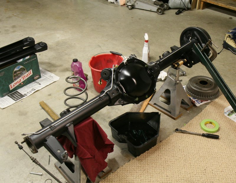
I also took the opportunity to re-detail the housing and clean up the
bodywork dust and overspray. The new-to-me 4 speed frame brackets were
also installed when the control arms were re-installed.
In the spring of 2013, the car was taken on it's maiden voyage
after
the restoration. I'm happy to report that the rear axle is super quiet
and functions perfectly!
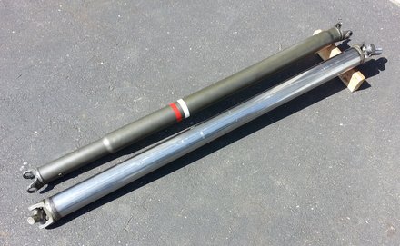
Driveshaft
April 23, 2014
I drove the Goat
a couple hundred miles in the summer of 2013, with just a little time
on the
highway, but I did notice a vibration at high speeds. I kind of
suspected the driveshaft because of the high-ish frequency. I
should have known because when I bought it off of ebay years
ago,
it had a shredded u-joint on one end. Sure enough, when I put the car
on jackstands, I could see that the driveshaft was running eccentric by
a good 0.060". I had no idea if this was fixable, so I did a
search for a local driveshaft shop and found CT drive-shaft in East
Hartford. I was hoping they could just balance it.
Chris,
the owner of CT Drive-shaft, told me to bring it down. After explaining
my problem, he mentioned some details about driveshafts running truer
than 0.010", and my heart sank; I knew my unit was toast. And yep,
that's what he told me later that day when I called back.
So,
after thinking about it, I decided I didn't want to mess with another
used driveshaft. Chris explained that he could make a really nice steel
unit that would be much better than the original unit. So he whipped
one up in mere hours after I asked him to proceed.
It's 3.5" steel with Neapco yokes. He re-used my new Spicer 3R
(saginaw) u-joints and Neapco slip yoke.
I
bolted it on and wow it sure runs nice. I thought about putting the
factory type stripes on, but since it's obviously a replacment unit, I
just clearcoated it. So the jittery convertible is a little less
jittery.
There exists a nice set of webpages for CJ3A's. It's got a forum too that caters to both '3A's and CJ3B's. It's a great resource, and frequented by very knowledgible folks.
1967 GTO Original Owner
These two videos feature an original owner GTO. This car was featured in Hemmings Muscle Cars magazine a couple years ago. Part 2 has inside and outside shots of the owner driving the car. Very nicely done.
Blues Maker
"Mississippi" Fred McDowell. One of the great Bluesman. This is a documentary made in 1969.
Pinstripes
Pinstriping the ol' fashioned way. Pretty nice.
MGB Racecar
I've always liked MG's. Watch this MGB lift it's inside tire a few inches off the tarmac when going "'round the bend". Awesome.
Pepsi Throwback
Pepsi has put out a "limited edition Throwback" version of
Pepsi with REAL sugar, instead of high fructose corn syrup which has been used since the 80's. Holy cow
there IS a difference; it's WAY better. Find some quick!