

Projects:
GTO
My
67 Pontiac GTO
Trunk Body Work
-Trunk pans
-Wheel wells
Body Work Part 1
-Rear Quarters
-Rear Door Jambs
-Window Reveals
Body Work Part 2
-Cowl
-Pillar
-Rocker
Body Work Part 3
-Windshield channel
-Doors
-Fenders
GTO Paint
-Filler work
-Priming
-Blocking
GTO Frame Work
GTO Convertible Top Pt 1
-Top Frame
GTO Convertible Top Pt 2
-Top Trim
GTO Drivetrain
-Engine
-Quadrajet Rebuild
-Exhaust
-Axle
Muncie
Rebuild
popular
Auto to Manual Swap
1967
Ram Air GTO
story
Wheelhouse Filler template PDF
Willys CJ3A
CJ3A Intro
Engine and REBUILD
Drivetrain
BodyWork 1
BodyWork 2
BodyWork 3
BodyWork 4
Paintwork 1
Paintwork 2
Final Assembly
Final Assembly 2
Electrical System
Other Rods
TJ Wrangler Rubicon
CJ7
CJ8
Triumph TR4
Decrepid Dakota
Powerdyne Minibike
Allis Chalmers B engine rebuild Part 1
Allis Chalmers B engine rebuild Part 2
Allis Chalmers Generator to Alternator conversion
Gizmos
Stereo camera
rig
Stereo mic preamp
About:

Feeds

Markup
Muncie Transmission Rebuild
 So
I got myself a
Muncie 4 speed to swap into my GTO. There's plenty of info on the 'net
for ID-ing
muncies so I armed myself with all the codes before shopping. I found
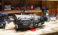
this particular muncie at a local
swap meet. I
didn’t really know what to look for mechanically so I just checked for
broken parts.
So
I got myself a
Muncie 4 speed to swap into my GTO. There's plenty of info on the 'net
for ID-ing
muncies so I armed myself with all the codes before shopping. I found
this particular muncie at a local
swap meet. I
didn’t really know what to look for mechanically so I just checked for
broken parts.
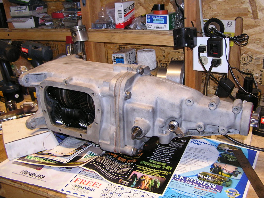
The trans I found was a 1967 vintage, so it has the large countershaft pin, the correct input shaft spline count for my other '67 vintage parts, and it also had the speedo on the passenger side which matches my TH400 automatic.
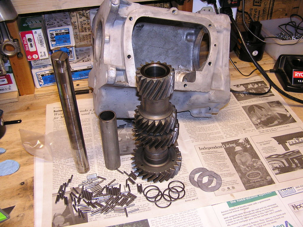
To Start
You'll need some sort of manual. I simply have an old Chiltons manual which lays out the whole process in very basic steps. It’s got a grainy exploded view so I searched for and found a nice exploded view at www.autogear.net. Go to the literature section, scroll down and you can download a great PDF file of Muncie parts with an exploded view. Study this exploded view. As you look at it, it may not all make sense, but when you tear down the trans, it will. Manual transmissions really are very cool mechanisms.
Some tools I found necessary: A small punch set, a brass drift set, and a “gorilla” class snap ring plier; it looks like a superduty duckbill for external snap rings. A 2 jaw puller is needed, and of course various hand tools.
Someone recommended a supplier of muncie parts to me so I sent some emails to Bob at www.fourgeartrans.com He was very helpful so I bought my parts from him.
Tear it down!
I didn’t follow any particular course of action, but just went carefully. Here are the main steps:
- Shift the transmission into two gears: Twist the shifter shafts CCW (front shaft puts it into 4th, back shaft puts it into 2nd) This locks up the mainshaft so it won’t spin. Take the front bearing retainer off.
- Take off the “gland” nut, otherwise known as the input shaft nut. There is a special wrench for this nut, which I did not have until later. Many use a monkey wrench (didn't work for me). I chucked the nut into my bench vise (not easy with a transmission attached) and turned the whole transmission by hand to break it loose. I later purhased the correct tool along with my rebuild parts.
- Shift the front fork shaft into neutral, (one click CW). Leave back fork shaft in second gear. This allows easy side cover removal.
- Remove side cover.
- Tap out the reverse gear shaft retaining pin with a punch. It’s on the side of the boss where the reverse lever enters the tail housing. Drive it out from the bottom up.
- Unbolt the tail housing. Pull out the reverse shifter fork shaft a little bit. Pull the tail housing off. Move it around to clear the reverse gear inside.
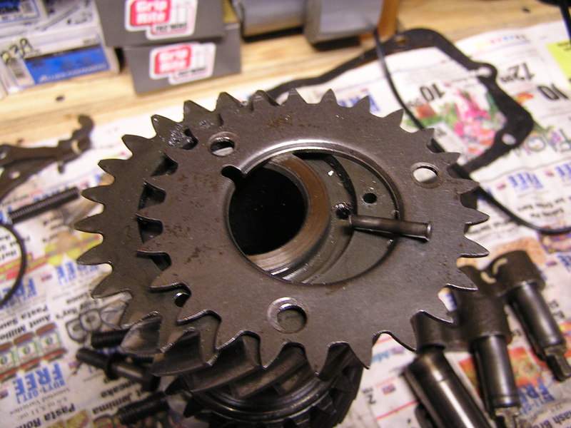
- Take out the reverse idler gear and shaft. Note the missing chunks out of the teeth.
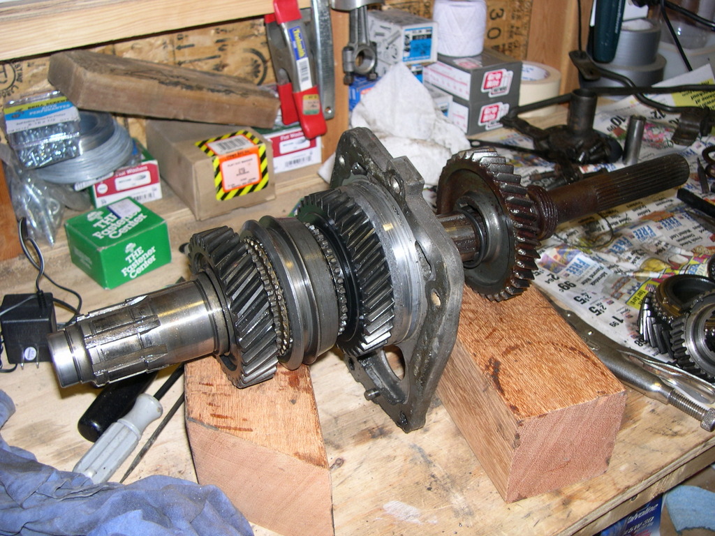
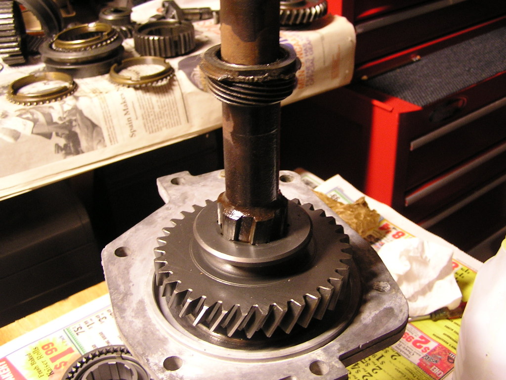
- Pry off the midplate from the main case and remove all the gear works and mainshaft as a unit. Roller bearings will fall out of the input shaft inside the case but that's okay.
- Once the mainshaft is on the bench, remove the front snapring. You’ll need to flex your gorilla arms to get this snapring off. Use the correct tool!
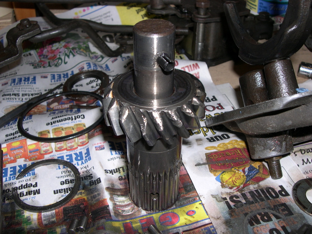
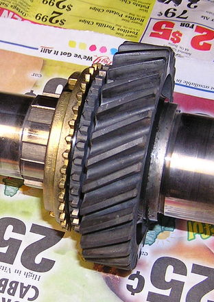
- Remove the slider/hub toward the front. I had to tap the hub off; it was a bit tight. Then remove 3rd gear. Here's the mainshaft with that removed:
- Remove the speedometer gear ring. I used a puller with homemade extensions to get the jaws to reach the ring. I also used heat (torch) because that speedo ring was TIGHT.
- Now you can slide off the big reverse gear.
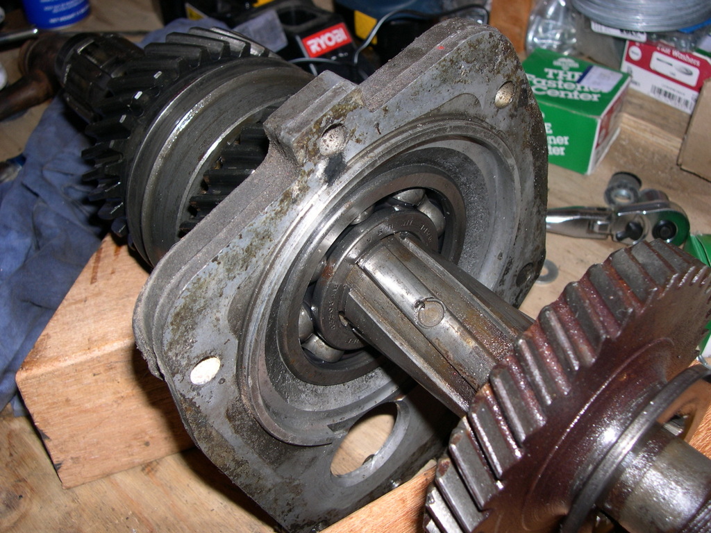
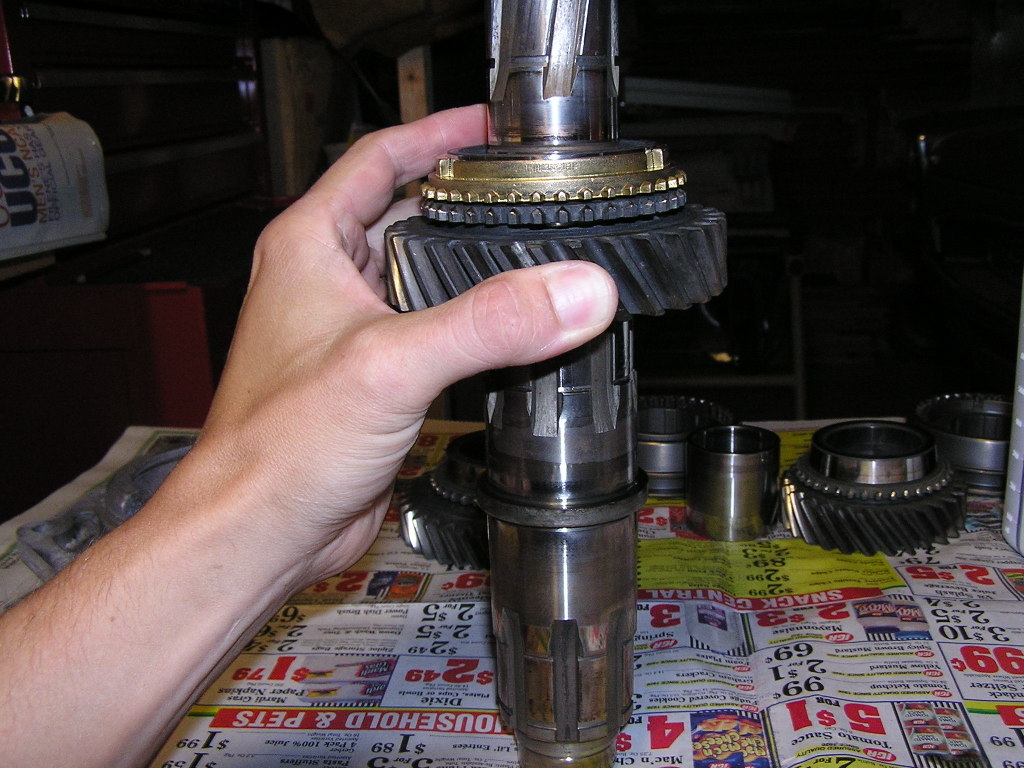
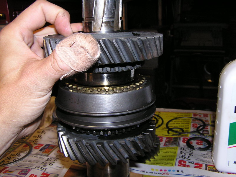
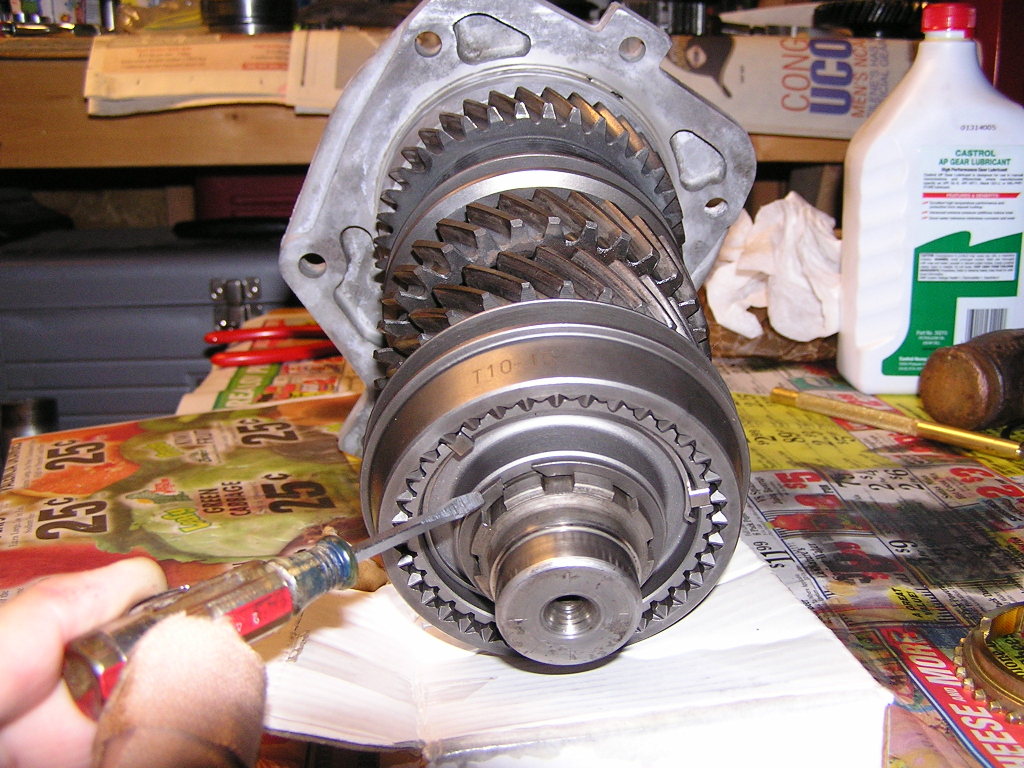
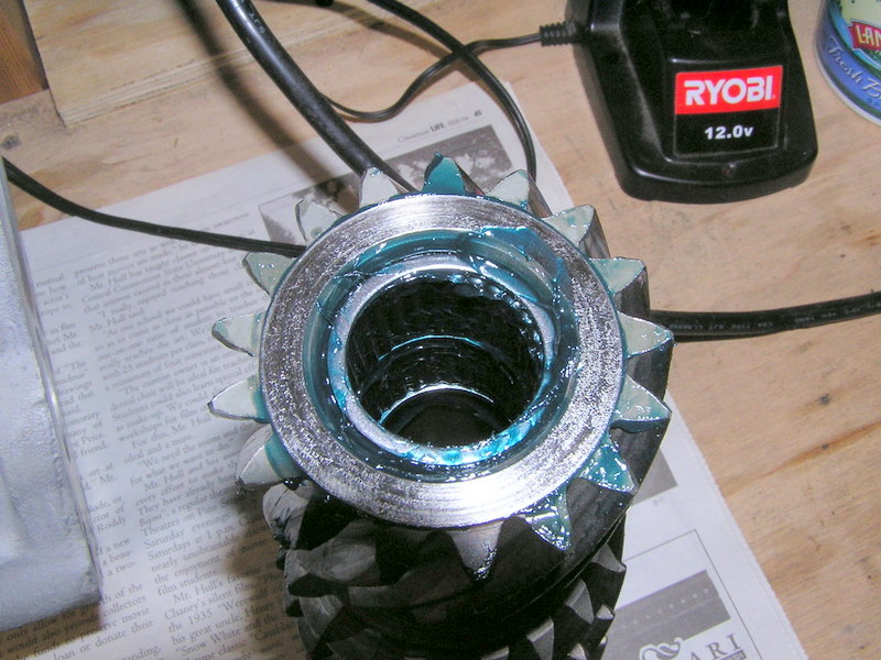
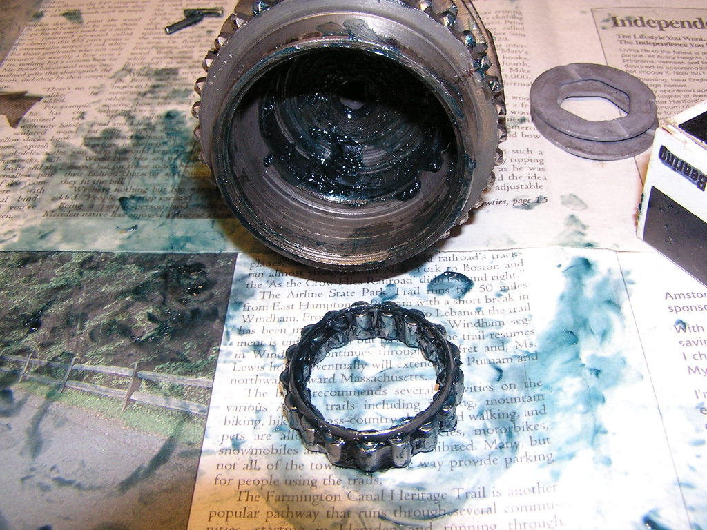
- From the back,
remove the
snapring just in back of the rear bearing inner race. This is a gorilla
class snapring too. In the photo below the snap ring has been removed
but note the groove where it resided.
- To continue, the rear bearing and press-fit first gear bushing need to be taken off the mainshaft. Some folks just take this to a machine shop to have these pressed off...another alternative is to take the assembly and smack the tail of the mainshaft onto an aluminum plate on a hard, non yielding floor a bunch of times to force off the parts. Maybe next time. Since I had it done at a shop with a press, they just emerged from out back with all my parts off. But if that's not your case, after pressing off the bearing and first gear sleeve, 2nd gear can now be removed. You should have a bare mainshaft now.
- To finish breakdown of the maincase: First, remove the reverse idler front gear and thrust washer. It’s hangin’ loose in there. Refer to your exploded view! You can now tap the input shaft into the case and take it out. Remove the bearing by tapping it out to the front using a drift from the inside. It shouldn’t be in there too tight.
- Now to remove the cluster gear (counter gear): Use a big brass drift and drive out the countergear pin from the front to back. After a few good hits it’ll slide right out. Lift the counter gear out. Lots and lots of needle bearing will pour outa there! Take out the bearings and spacers and thrust washers too.
- There may be a sheet metal “gear” riveted onto the front of the gear. It’s some sort of anti-rattle mechanism, but I read that it’s been known to come apart and destroy the main case. Apparently it's not a necessary part; it's to make the trans a wee bit quieter. To remove, I drilled out the rivets and removed it.
- It's time to wash all the greasy internal parts as
well as the case. Once clean, a thorough inspection sould reveal what
you need for a good rebuild. The bare bones kits come with new needle
bearings, seals, and synchros. But depending on damage, you
can add anything else you need. Replacing the cheaper parts is a
no-brainer, but it starts to get expensive quick when it comes to
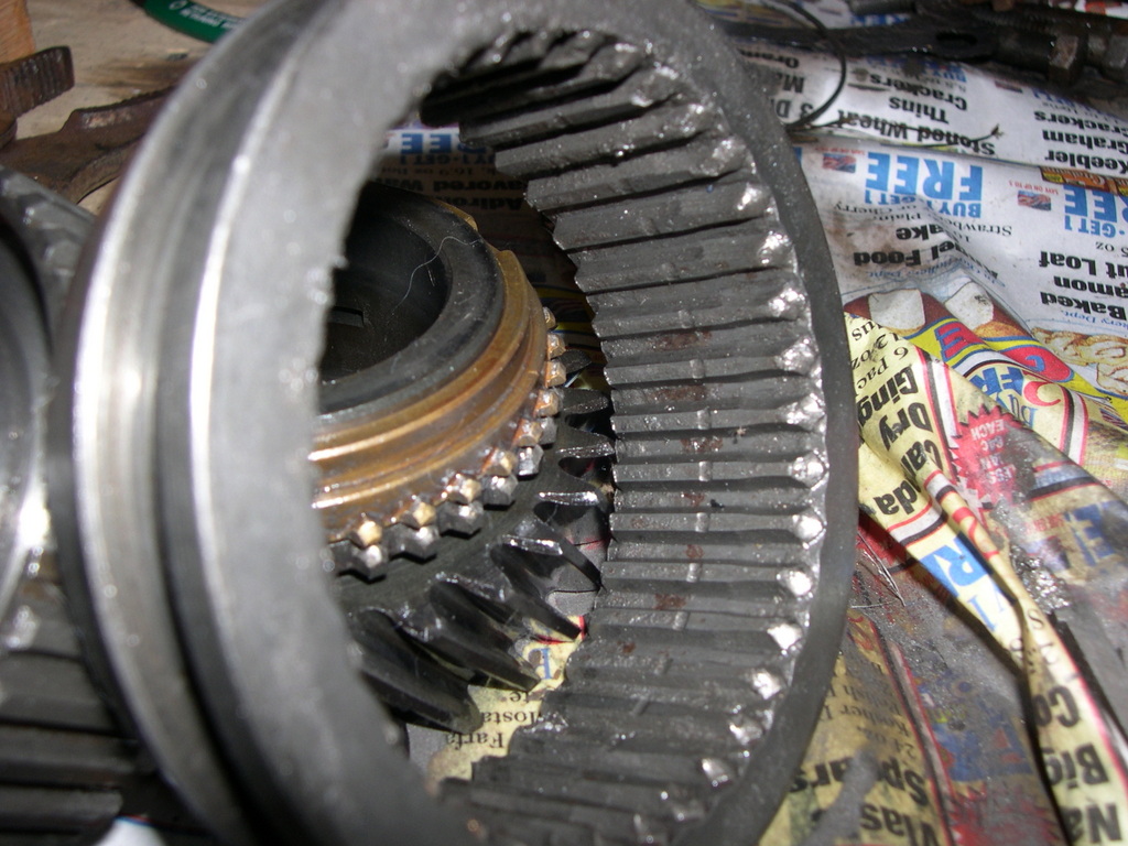
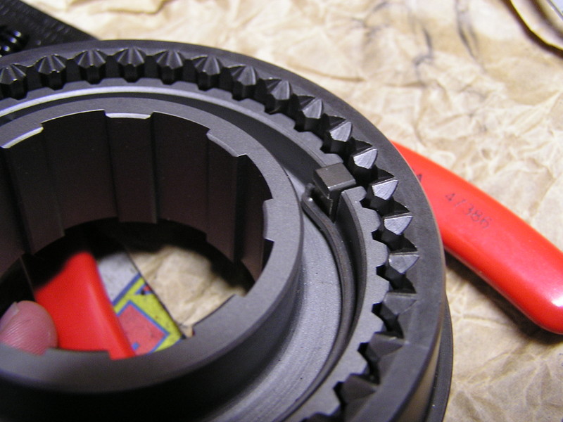
gears. My gears were in good shape,
although the engagement teeth on third gear were a bit rounded off. The
engagement
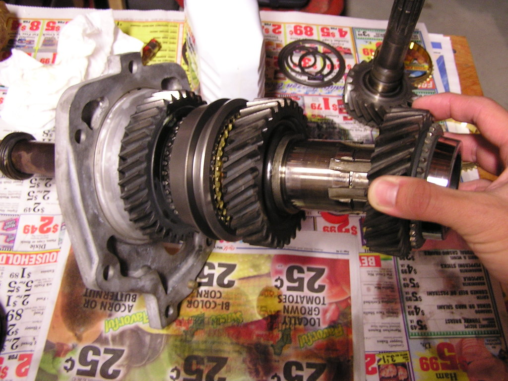
teeth are the little nubs on the "cone" side of the gear. In the
picture below, the brass "blocking ring" (colloquially known as a
"synchro") is installed on the "cone" of the gear (so you can't see the
cone) but you can see the engagement teeth next to the synchro:
The "sliders" are shifted back and forth to grab these teeth depending on which gear is engaged. The sliders have internal splines to engage these teeth on both the synchro's and gears. If the engagement teeth, slider engagement splines, or both, are worn, the gear will push the slider off its engagement teeth which basically means it pops out of gear.
(By the way, reverse gear is not "synchronized', hence no synchro, cone, or engagement teeth.)
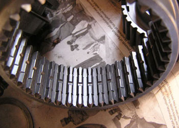
Here's a view of worn out slider splines I found on my transmission:
The splines on good condition original style sliders should be straight.
The corresponding engagement teeth on my gears were also worn, but they didn't look too bad. There was no question about replacing my worn out sliders, but replacing all my gears was a bit more worrisome due to the potential expense.
I talked to the Fourgeartrans guy and he recommended Torque loc sliders. These help keep your gears engaged especially if your gear’s engagement teeth are a bit worn. Normal sliders are straight splined. Note the Torq-loc splines.
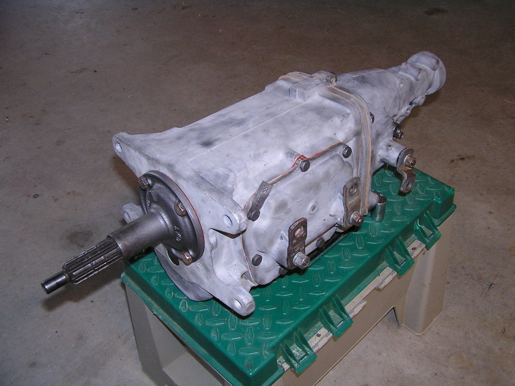
I sandblasted all the case parts since they were really stained and dirty. I tried chemicals, but the finish was still stained and ugly. I used fine Olivine blasting sand. Lot's of work but it looks good.

I repaired a stripped trans mount thread in the tailhousing with helicoil, and also patched a break through in the tail housing caused by a excessive length bolt used on the shifter mounting plate. I used JB Weld epoxy to seal it up. This is good stuff!

So get your rebuild kit and let’s get started on the...
Rebuild
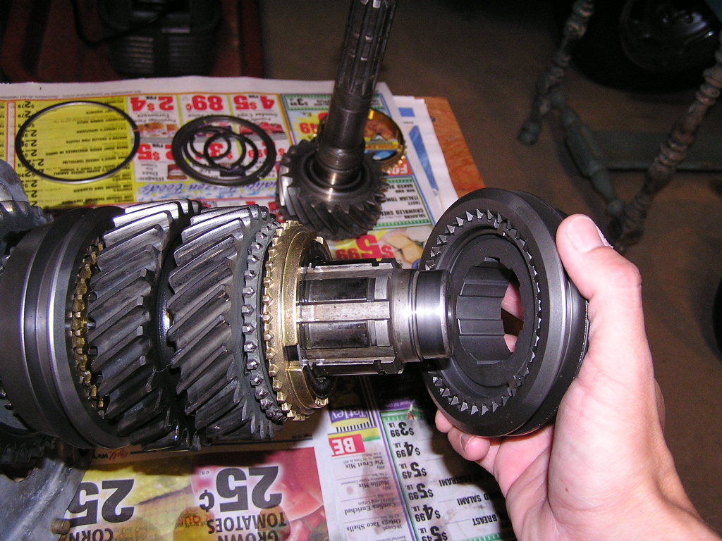
- Assemble your synchronizers. The synchro hubs have a flat side and an extended side. The extended side will face front for both 3rd/4th assembly, and 1st/2nd assembly. The slider (i.e. sleeve, i.e. clutch) for the 3rd/4th set is slipped over the hub so the tapered side of the slider faces front. The 1st/2nd slider in slipped over its hub so the the slider taper faces the rear.
Take a look at the assemblies here. 3rd/4th is to the left, 1st/2nd is to the right. Hubs are already inside the sliders. Finger points to hub extension. The analogy used frequently is the assemblies stacked together look like “a hamburger bun” as you look at it.

This detail shows the spring holding the key in place. The spring holds all three keys in. It is the same on the other side. Note the orientation of the keys.
- Put some oil on the main shaft and slide on second gear with a brass blocking ring (some people refer to this as "the synchro"). Cone side of gear faces rear of shaft.
- Slide the synchronizer assembly (the one to the right in the previously shown photo of the synchronizer hub pair) onto the mainshaft with the hub extension toward the front. This may have to be tapped on. I used a brass drift. Make sure the brass blocking ring is aligned so the keys from the synchronizer assembly fit into the brass blocking ring's 3 wide gaps. While tapping it on be careful you don't dislodge the keys.

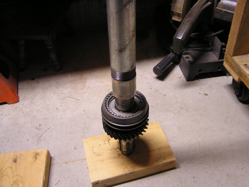
- Now the 1st gear bushing can be pressed on. Since I don't have a press, I used a 2 foot length of 1-5/8 I.D. steel pipe and a small beating shallilly to pound it on.
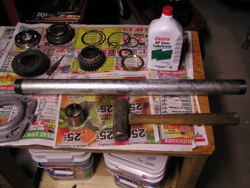
Note the pipe pressing the sleeve down to the syncronizer assembly hub. Make sure you tap it down all the way.
- With the shaft tail sticking up in the air, install a brass blocking ring into the synchronizer assembly, being careful to align the notches with the keys, then lube up the I.D. of first gear and slip it onto the bushing.
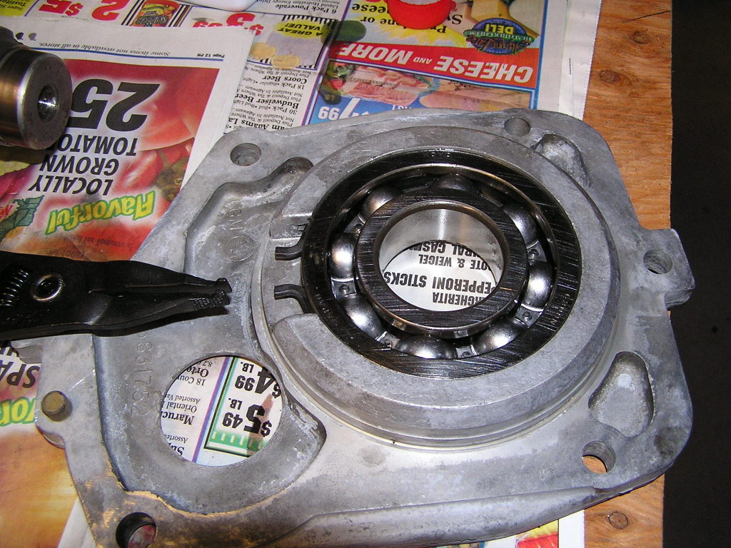
- Time to press the rear bearing into the midplate (rear bearing retainer). Put in the bearing snapring first, expand the snapring and press the bearing into place. Press it in until the snapring snaps into place. Tapping may be necessary. Make sure the bearing is facing the right way or it'll be sticking out of the midplate.
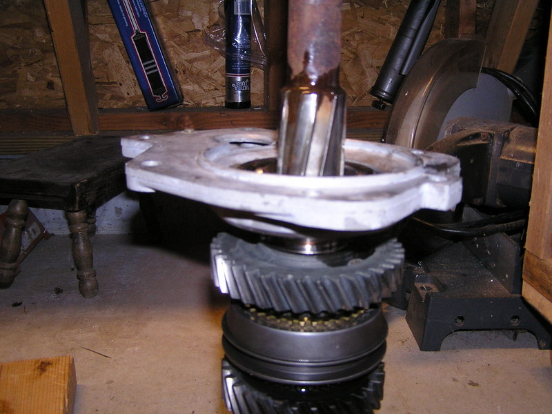
- Place the midplate onto the mainshaft and press the bearing down until it hits the first gear bushing. Here also, you may need the help of a hammer and pipe.
- Install a snapring in the groove directly behind the rear bearing. The rebuild kit should have several thicknesses. Pick one so it's as small a gap as possible when installed. Place it so the ends are behind splines.
- Install the reverse gear with the flange facing toward the end of the shaft. Install the speedometer ring. Hammer the ring into position; I used the old input shaft nut as a washer in between the pipe and speedo ring so I wouldn't bugger up the speedo ring teeth.
- Test fit the tailhousing onto the midplate and look to verify the speedo ring is lined up in the middle of the speedo cable hole.
- Time to install the 3rd and 4th gears onto the front of the mainshaft. First, oil up the I.D. of 3rd gear and slip it onto the mainshaft with the cone facing forward.
- Install the synchro assembly with the hub extension facing forward also. This may need to be tapped on with some slight persuasion too.
- Now the front snapring can be placed on. Orient the snapring so the ends are behind a spline.
- Your assembly should now look like this:

- Time to get to the maincase and cluster gear. Get your jar of grease ready. Study your exploded view for the sequence of parts.
- Pack some grease into the cluster gear center and place the long spacer inside. Place a single thin washer in, then smear grease around the inside. Start packing in the roller bearings. Pack as many as will fit. Place another thin washer on top and press the works inside. Smear more grease around the inside, then pack more roller bearings (as many as will fit). Place yet another thin washer on top and press it flush with the end of the counter gear.
- Go to the other side of the counter gear and put a thin washer in there, smear some grease, pack in roller bearings, another thin washer, more bearings, then the last thin washer. Note the roller bearings inside the cluster gear.
- Apply grease to the back side of a thrust washer. These have a tab which fits inside the notch in the case. Squash them into place on each end of the case.

- There seems to be many methods to do this next part. Many have said it takes many tries, but I found it to be very easy for some reason. Here's what I did:
- Place the main case so the front end is on the bench top.
- Manuever the counter gear into position with care. Ensure that the thrust washers stay in place. Use a screwdriver or your fingers to put the thrust washers into postion.
- Take the countershaft pin, flat end first and push it down into the countershaft hole. Wiggle the countergear to help it along. The pin should go all the way except for the last half inch or so.
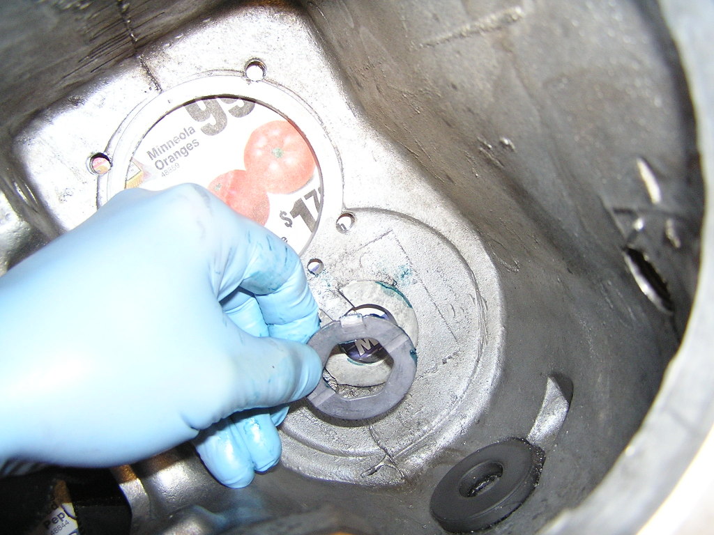
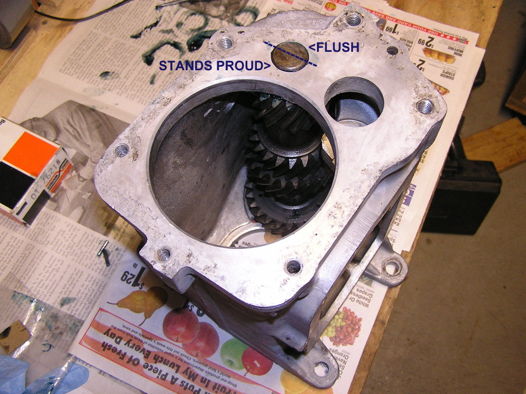
- While holding the countergear with one hand, tip the case on its' side and use a finger to align the front thrust washer and guide the pin to the front hole in the case. Once it finds the hole, it will need to be pressed the rest of the way. BEFORE YOU DO: Make sure the pin is aligned correctly. On the rear part of the case, the raised part of the pin is up and as you look at it from the rear. It should aligned to the 8:00 o'clock and 2:00 o'clock positions. See Figure 20.
- Tap the pin in until the notched part of the pin is flush with the case.
- Now place the case on its side and install the front reverse idler gear thrust washer. It also has a tab which mates with a notch in the case.
- Install the front reverse idler gear. It will be loose for now until the rest of the guts are installed.

- Load the input shaft bearing cage with their roller bearings. They are installed from the outside. Grease will hold them in.
- Load up the input shaft roller bearing area with grease and slip the cage and roller bearings inside.
- Place the last blocking ring into the 3rd/4th synchro. Make sure the notches line up with the keys. Place the input shaft assembly onto the mainshaft. The insider roller bearings will slip over the mainshaft tip.
- Slip the front midplate gasket into position. I used a thin bead of silicone to keep it in place.
- Apply a bead of slicone to the back of the maincase.
- Lift the gear assembly into position at the rear of the main case. Put your hand inside and guide the gears/mainshaft into the case. Keep going until the midplate is against the main case. Align the dowel pin and then tap the midplate until it is seated. Since I was taking my time and I wouldn't get to the tail housing until later, I used some bolts to snug it all down to "seat" the gasket and silicone. I let it sit overnight to cure.

- Slip the reverse idler pin into a liberally oiled reverse idler gear. Slip it into the case and manueuver the front idler gear so the splines engage. Be careful to make sure the tabbed thrust washer stays in place inside the main case.
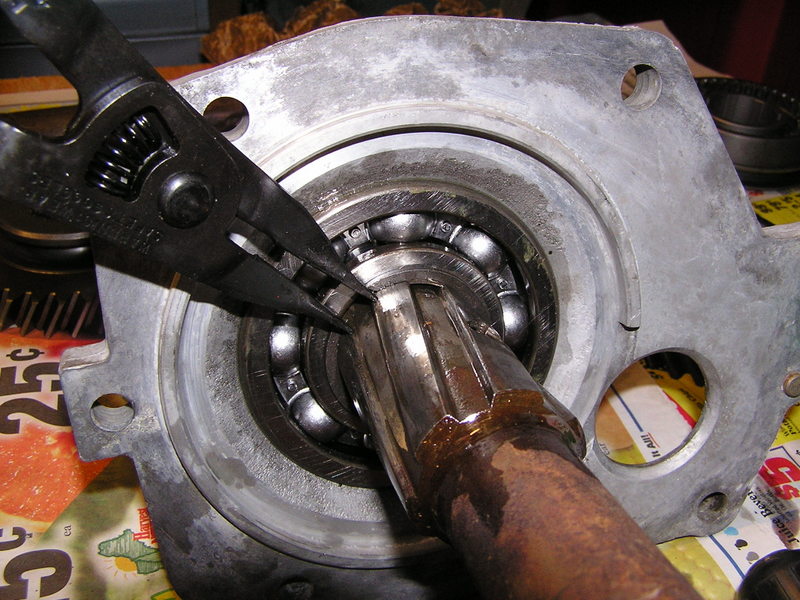
- Time to install the front bearing. Place the snap ring onto the bearing. Place it over the input shaft and press or tap it down until it seats in the main case.
- Lock the transmission into two gears. This will keep the mainshaft/input shaft from turning.
- Install the left hand input shaft nut. Tighten it up. I bought the correct wrench, even though it was a bit pricey. I don't want to monkey with a monkey wrench for this one. Use loctite, and/or stake the nut to the mainshaft.
- Install the gasket on the bearing retainer. I used slicone on the gasket. Align the retainer so the oil drain path is correct then bolt it on. Use sealer on the bolts!
- Tail housing time: Press or hammer out the yoke bushing. I used a 1-1/4 inch socket which fit perfectly. Install the new bushing. I used a piece of hard wood to start it, then as it went below the outer seal lip, I used big washers to hammer on. Drive it in until it is flush.
- Install the rear seal.
- Install the seal for the reverse lever shaft. A 3/4 socket is perfectly sized to tap it in.
- Install the spring and ball bearing (inside the tail house case)into the hole for the reverse lever.
- Install the reverse lever as far as it will go. The lever must be pressed in so the ball is bearing against the detents on the shift arm.
- This gets tricky: How do you press the spring and ball down and push the reverse lever in all the way? I used a piece of shim from a feeler guage set to use it like a shoe horn. It worked very nicely, but the shim was slightly mangled. (When is the next time I'll need an 0.008" feeler guage anyway?)
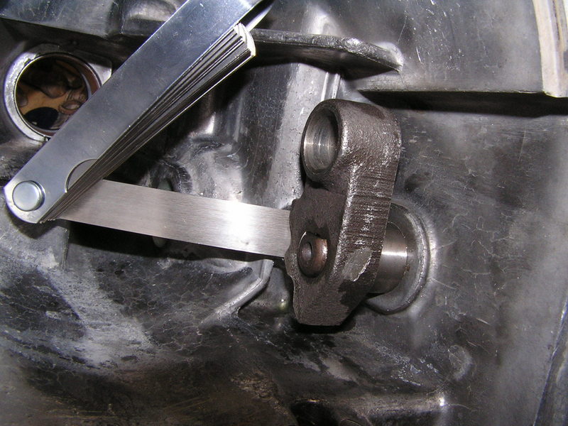
- As seen above, the reverse lever still needs to be pushed closer toward the wall of the case about 3/8 of an inch. But don't push it in too far yet.
- Rotate the reverse shifter arm forward so the ball bearing is pressing on the bottom detent. This is the engaged position for reverse gear.
- Now pull the reverse lever shaft out of the case as far as possible, but be very careful not to let the ball bearing spring out past the lever. The lever needs to be in this position to allow the tail housing to slip onto the main case and reverse gear while you install the tail housing.
- Place the reverse shifter fork (forklet?) into the reverse shifter arm. Align it so its slot is vertical.
- Slip the gasket onto the midplate.
- Move the reverse gear out to the rear of the splines it rides on (reverse gear disengaged).
- Manueuver the tail housing over the tailshaft and line up the fork over the reverse gear flange. Once the fork is on the flange, align the reverse idler shaft into the tail housing and then push the tail housing on all the way. Tap the tailhousing the last bit if needed, but don't force it.
- Push the reverse shifter shaft into the case now so you can see clear through the hole the tapered retaining pin goes into.
- Make sure the 1/2 and 3/4 synchros are in nuetral, and then rotate the input shaft and see if it is indeed in reverse.
- With pliers, rotate the reverse shifter shaft CW. This disengages reverse and you should now be in true neutral.
- Install the tapered pin to lock the reverse shifter shaft into position.
- Time to assemble the shifter cover plate. Install the seals in the shifter plate. A 3/4 socket works nicely.
- Install the detent levers.
- Install the spring.
- Install the shifter shafts with forks. Pull the detent levers up to push the forks in all the way. Leave the 1st/2nd lever rotated toward the left, or 2nd gear position.
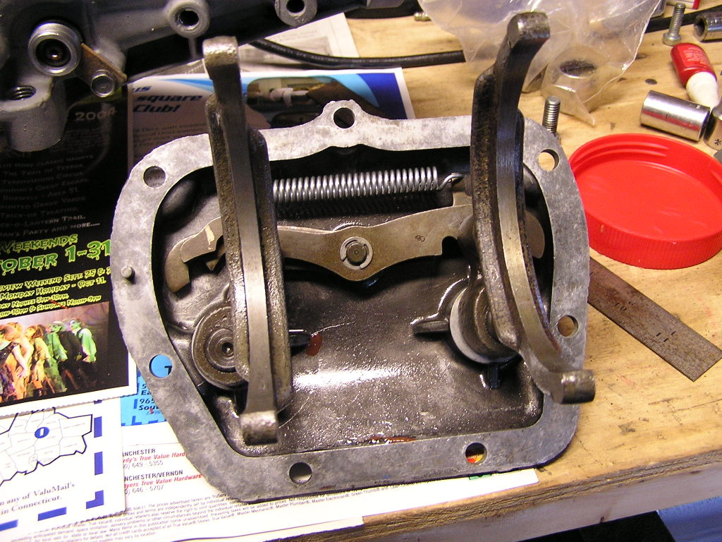
- Place the shifter cover gasket in position and manuever the cover on. Install all the bolts and torque them on.
- Install the speedo driven gear housing.
- Rebuild complete! DON'T FORGET TO FILL IT WITH OIL BEFORE YOU FIRE IT UP!
This was a very rewarding project and really was pretty easy. If you have any feedback, I'd appreciate hearing from you. See my About page to get my email address.
UPDATE!
June 30, 2013
The restoration of the car this trans was intended for took quite a while and was not installed and run until 2013, something like 7 years after the rebuild featured above.
After taking it for it's first drive, it was obvious the Muncie transmission had a loud whine in the reduction gears and neutral. I remember noting this when turning by hand years ago and an acquaintance said it was no problem. But after hearing it run, and also noting the speedometer did not work, I was compelled to jack up the car and drop the tranny.
Initially, I wondered if it was about having no oil slinger on the input shaft, or perhaps a bad bearing. But everything was fine when I ripped it open. And the oil slinger or shims should have nothing to do with noise. I decided to get some expert eyes on it.
I consulted with Dave Reed of Reed Performance Transmissions in Wallingford CT. Mr Reed offered to look at it immediately. I took it to his shop and in 2 seconds he knew what the problem was: Completely toasted gears. All of them. It was something that I just didn't recognize due to my inexperience with gears.
Insert closeup pic of old countergear here....
The trans must have been run for a long time with low oil, and all the gear teeth had scallops on the flanks. This made for a obnoxious whine in first, second and third gears. Now that I look at it, it seems obvious.
Dave Reed was really helpful and we spent quite a while talking transmissions. He also noted that the mainshaft seemed to have the wrong speedometer ring on it. It turns that in addition to there being different tooth count speedometer rings, there are a few different diameters. I needed the larger 1.84" diameter ring to work with the 19 tooth plastic driven gear. (I had the 1.76" diameter previously.)
After going over some options I decided to buy a set of Autogear wide ratio "Rockcrusher" gears.
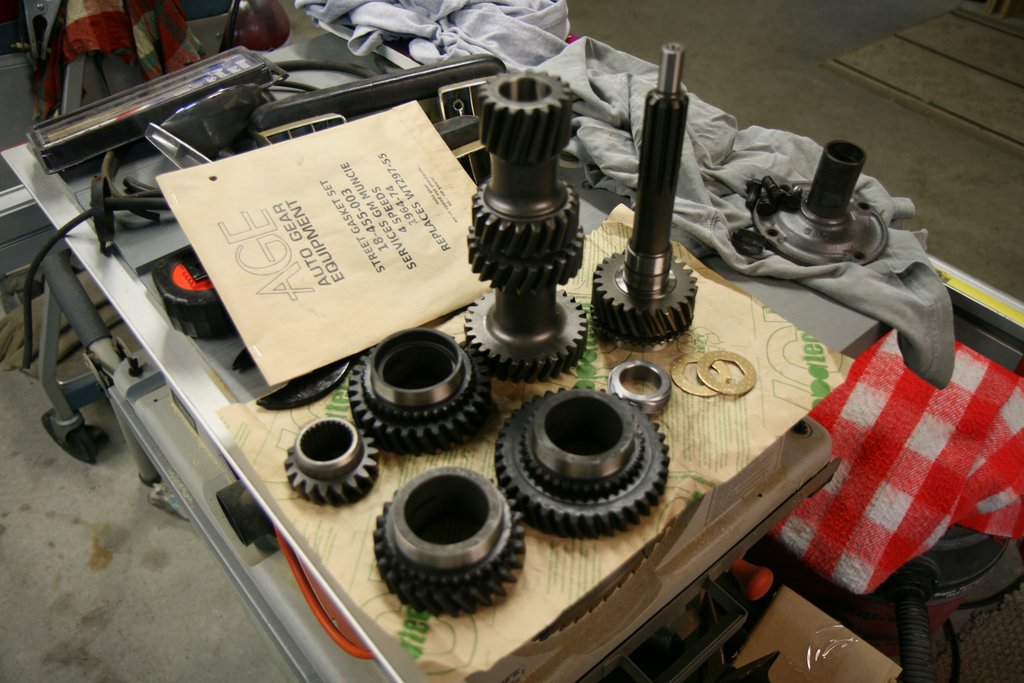
Reed sells all the Autogear stuff. This set of Italian made gears is known as the M22W gearset, "W" standing for wide ratio. (Original rockcrushers were all close ratio.) My brief time with the M20 confirmed that the wide ratio works really nicely with the 3.36 rear ratio. Also note in the picture a new set of countergear thrust washers. Dave told me that many kits only have solid steel washers which are not optimum, so I got a couple of dimpled bronze washers from him.
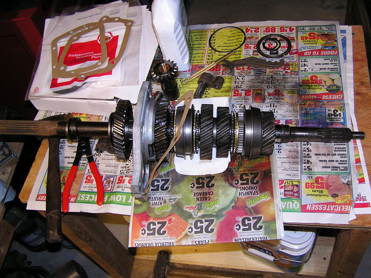
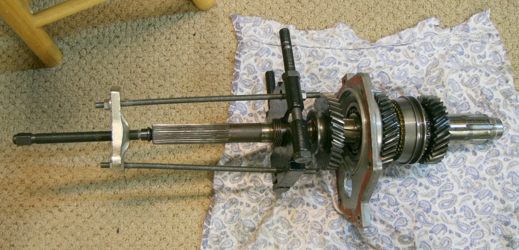
The transmission was taken completely apart. This time I had a bearing separator and threaded rod which made it easy to remove the incorrect speedometer ring. That ring has to come off anyway to replace all the gears.
Here's the mainshaft populated with the new gears. Note the "straighter" cut of the gears; they are not angled as steeply as the regular M20 gears. This reduces end-loading of the countergear, which reduces heat. The "price" you pay is slightly noisier gear mesh at speed. But that only matters when in reduction gears. 4th gear, which is 1 to 1 ratio, is quiet as there is no load on any of the gears. Note also the new speedometer ring.

I also took this time to put in a proper 1/2" NPT drain in the maincase. The trans was finished up and reinstalled.

Ahhh, what a pleasure it is now. No undo noise. It's got a pleasant, subtle whine. It's the rockcrusher sound. The shifting is a bit balky, but with everything new, I think it will take a summer to break it all in.
Any comments please email me:
SFS
Links:
Willys Jeep CJ3A Forum
There exists a nice set of webpages for CJ3A's. It's got a forum too that caters to both '3A's and CJ3B's. It's a great resource, and frequented by very knowledgible folks.
1967 GTO Original Owner
These two videos feature an original owner GTO. This car was featured in Hemmings Muscle Cars magazine a couple years ago. Part 2 has inside and outside shots of the owner driving the car. Very nicely done.
Blues Maker
"Mississippi" Fred McDowell. One of the great Bluesman. This is a documentary made in 1969.
Pinstripes
Pinstriping the ol' fashioned way. Pretty nice.
MGB Racecar
I've always liked MG's. Watch this MGB lift it's inside tire a few inches off the tarmac when going "'round the bend". Awesome.
Pepsi Throwback

Pepsi has put out a "limited edition Throwback" version of Pepsi with REAL sugar, instead of high fructose corn syrup which has been used since the 80's. Holy cow there IS a difference; it's WAY better. Find some quick!